Project System For Teensy 4.1
$86.95 – $199.95
Platform for building a project based on the Teensy 4.1
Description
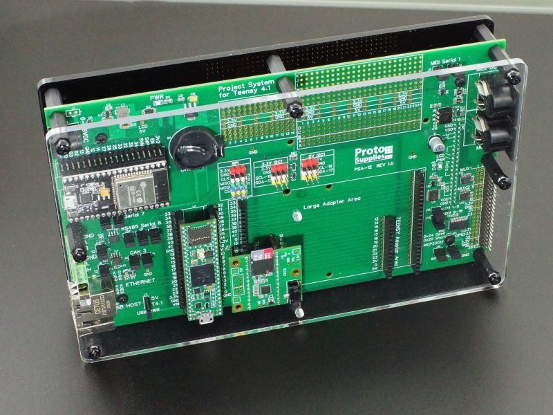
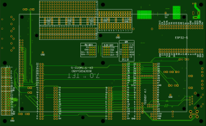
The Project System for Teensy 4.1 is designed to provide a flexible setup to help in the creation of a finished touch LCD based project using the powerful Teensy 4.1 microcontroller.
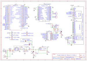
The baseboard provides the core features required in many setups including power input handling, touch screen LCD for user interface and access to common buses and interfaces such as Ethernet, USB Host, CAN bus, RS485 bus, I2C, 5V I2C, SPI, MIDI, WiFi and Bluetooth.
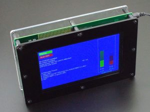
It has some things in common with our Prototyping System for Teensy 4.1, but is more geared towards building a 1-up finished project rather than prototyping many projects. A major difference is that it uses a much larger 7″ LCD that mounts on the back side of the baseboard. It also has analog and digital I/O expansion built-in as well as an area to mount 3rd party modules. Acrylic panels are also available to provide a semi-finished enclosure with open sides for easy I/O access suitable for finishing many projects.
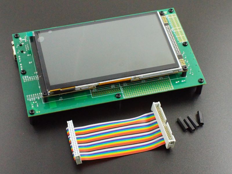
During development, a 4″ male/female extension cable is provided to allow the display to lay next to the baseboard for easily working with the setup during system integration. In this configuration, it can be used much like the Prototyping System and even used in place of it, but it does take up more bench space. The LCD has been operated on up to a 50cm (19.7″) extension cable without any issues noted, so the LCD could be remotely mounted to a more convenient place if desired.
The LCD used with this baseboard is the BuyDisplay ER-TFTM070-5 with Pin Header Connection – 4-pin SPI, 5V operation and 7″ Capacitive Touch Panel with Controller options selected.
No MicroSD card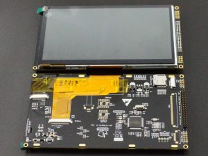
This LCD is the best supported of the larger size LCDs on the Teensy 4.1.
The LCD can be ordered directly from BuyDisplay for $60-$90 with shipping depending on how fast you have it shipped.
We optionally include one with our baseboard below for about $73 along with an extension cable and mounting standoffs. We do not sell the LCD separately from the baseboard.
The Project System for Teensy 4.1 is Available in Three Versions
These are selectable at the top of the page or you can order in-line below. Please note that since the Teensy 4.1 can be configured in several different memory configurations, it needs to be ordered separately from the baseboard down below.
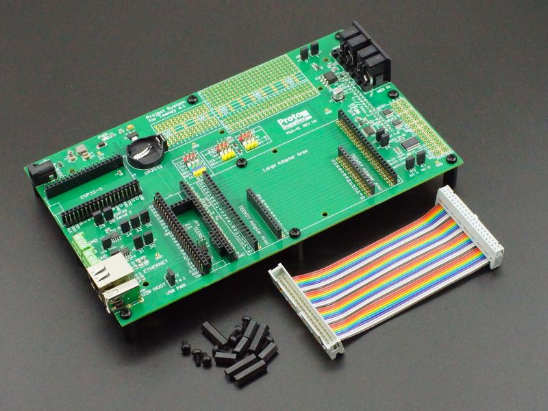
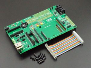
The Baseboard Only is the fully assembled baseboard with all SMD and thru-hole parts installed along with M4 x 20mm nylon standoffs and screws to provide support when working with it on the bench. It allows you to build your own setup by selecting from the various options below or combining it with parts already laying on your project bench. For some projects, the baseboard may be useful without the need for installing an LCD at all.
The Baseboard Only version includes the following:
- Project System for Teensy 4.1 baseboard
- Qty 9 – M4 x 20mm nylon standoffs and screws.
- Qty 4 – M3 x 11 LCD mounting standoffs and 8 screws.
- 4″ LCD Extension Cable for working with the display next to the baseboard.
- Qty 4 – m3 x 22mm LCD standoffs when working with it on the bench on the extension cable.
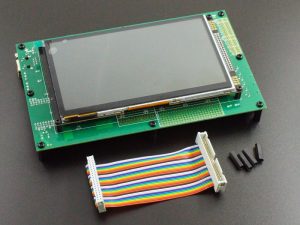
The Baseboard with LCD option is the same as above, but also includes the 7″ LCD that the baseboard is designed to work with as well as an extension cable and standoffs to lay the LCD next to the baseboard during system development. The LCD comes mounted to the baseboard for shipment.
The Baseboard with LCD version includes the following:
- Project System for Teensy 4.1 baseboard with standoffs and screws as noted above
- 7″ RA8875 TFT color 800×480 RGB SPI display with capacitive touch screen
- Qty 4 – M3 x 11 LCD mounting standoffs and 8 screws.
- 4″ LCD Extension Cable for working with the display next to the baseboard.
- Qty 4 – m3 x 22mm LCD standoffs when working with it on the bench on the extension cable.
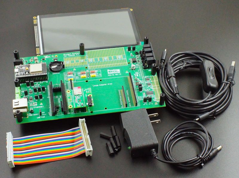
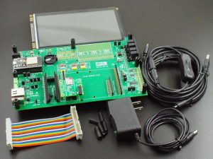
The Fully Stuffed option comes with everything installed and includes all the accessories needed to basically just plug and go. The ultimate in instant gratification. Just add the Teensy 4.1 of your choice from the list down below and the optional acrylic panels to complete a fully functional setup.
The Fully Stuffed version includes the following:
- Project System for Teensy 4.1 baseboard with RA8875 LCD as listed above
- ESP32-S WiFi/Bluetooth coprocessor
- Teensy 4.x Rev D Audio Adapter with pins installed
- 7.5VDC AC/DC adapter
- In-line DC power switch
- 32GB Sandisk SD card with PJRC example .WAV files preloaded along with the example programs below
- MicroSD to SD adapter
- 2 6ft USB Micro-B cables for working with both Teensy 4.1 and ESP32-S at the same time
Optional Acrylic 2-Panel Enclosure
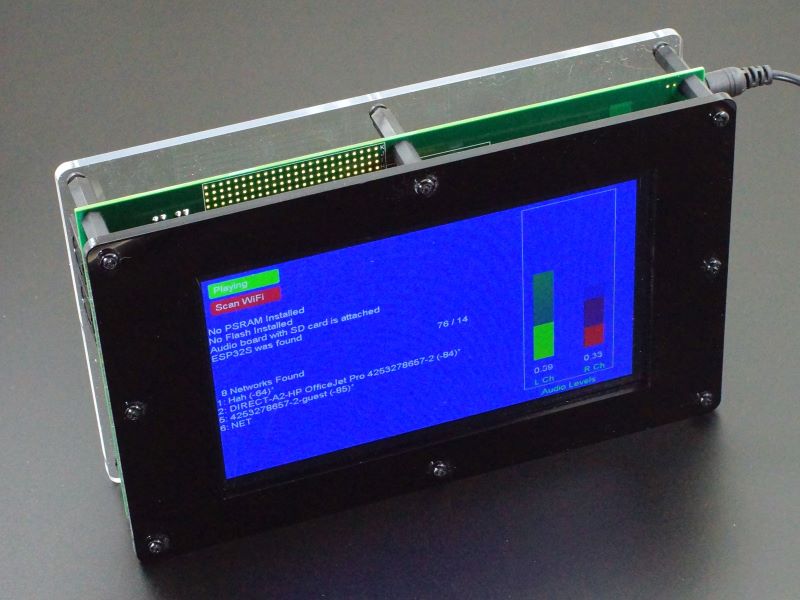
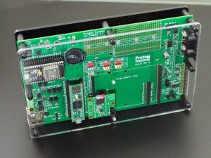
Because of the 2-sided nature of this product, once the LCD is permanently mounted to the back (front?) of the PCB and ready to be put into permanent use, it will probably want to be in some kind of enclosure or at least have standoffs installed on the Teensy side to provide mechanical support. We offer a low cost 2-panel acrylic case with open sides and nylon standoffs and screws for sandwiching the baseboard that will work well enough for many applications. The kit includes:
- Front panel in 4.5mm thick black acrylic with LCD cutout and mounting holes
- Back panel in 4.5mm clear acrylic with screw terminal slot and mounting holes
- Qty 8 – M4 x 18 M/F black nylon standoffs
- Qty 17 – M4 x 10 black nylon screws
- Qty 2 – M4 black nylon nuts
For more product information click on the picture
Teensy 4.1 Options
Add your choice of Teensy 4.1 from the memory configuration options below. If you order the Fully Stuffed version the system will be fully assembled with the example software preloaded. Just apply power and the system will come up and run the example code.
Select From the Following Teensy 4.1 Memory Configurations
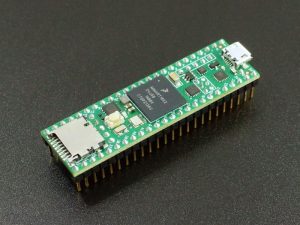
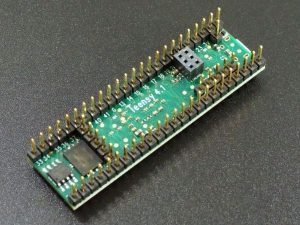
The Teensy 4.1 Fully Loaded for Prototyping System have all the headers installed to properly mate up with the connectors on the baseboard. VUSB trace is cut and a Schottky diode installed to properly isolate power. The same configurations are used for both our Prototyping System and our Project System baseboards.
These memory configurations can be selected below:
- No Additional Memory
- 16MB/128M-bit PSRAM with no Flash
- 8MB/64M-bit PSRAM & 16MB/128M-bit Flash
- 8MB/64M-bit PSRAM & 128MB/1G-bit NAND Flash
- 8MB/64M-bit PSRAM & 256MB/2G-bit NAND Flash
All memory is installed and tested.
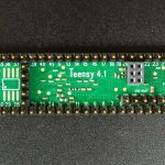 DEV-26-B - Teensy 4.1 Fully Loaded For Prototyping System – No Added Memory$40.95 Qty DEV-26-B - Teensy 4.1 Fully Loaded For Prototyping System – No Added Memory$40.95 Qty Max: 11 Min: 1 Step: 1 ADD TO CART |
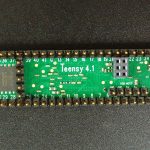 DEV-26-2G - Teensy 4.1 Fully Loaded For Prototyping System – 8MB PSRAM/256MB Flash$56.95 Qty DEV-26-2G - Teensy 4.1 Fully Loaded For Prototyping System – 8MB PSRAM/256MB Flash$56.95 Qty Max: 12 Min: 1 Step: 1 ADD TO CART |
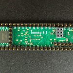 DEV-26-1G - Teensy 4.1 Fully Loaded For Prototyping System – 8MB PSRAM/128MB Flash$52.95 Qty DEV-26-1G - Teensy 4.1 Fully Loaded For Prototyping System – 8MB PSRAM/128MB Flash$52.95 Qty Max: 5 Min: 1 Step: 1 ADD TO CART |
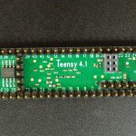 DEV-26-P - Teensy 4.1 Fully Loaded For Prototyping System – 16MB PSRAM$48.95 Qty DEV-26-P - Teensy 4.1 Fully Loaded For Prototyping System – 16MB PSRAM$48.95 Qty Max: 12 Min: 1 Step: 1 ADD TO CART |
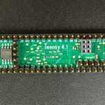 DEV-26 - Teensy 4.1 Fully Loaded For Prototyping System – 8MB PSRAM/16MB Flash$48.95 Qty DEV-26 - Teensy 4.1 Fully Loaded For Prototyping System – 8MB PSRAM/16MB Flash$48.95 Qty Max: 6 Min: 1 Step: 1 ADD TO CART |
You can click on the picture above to see more info on this build configuration of the Teensy 4.1.
Note: Memory configurations above are shown in Megabytes (MB) while some chip manufacturers are now specifying memory size in Megabits (Mb) or Gigabits (Gb). The use of a capital B means Byte while lower case b means bit. Since there are 8 bits in a byte, to convert from MB to Mb (or Gb), multiply by 8. The 256MB Flash for instance is the same as 2Gb.
What if I Already Have A Teensy 4.1 That I Want To Use With This Baseboard?
If you already have a Teensy 4.1 that you want to use with this baseboard, it is fairly easy to adapt to it with nominal thru-hole soldering skills and some header pins. There are instructions toward the bottom of this page.
KEY FEATURES OF PROJECT TYPING SYSTEM FOR TEENSY 4.1:
- All I/O brought out from the bottom of the Teensy 4.1
- Supports an optional ESP32-S co-processor for WiFi and Bluetooth connectivity
- Supports 7” 800 x 480 SPI capacitive touch LCD for user interface (BuyDisplay ER-TFTM070-5) on SPI1
- Built-in CAN bus transceiver on CAN3
- Built-in RS485 transceiver on Serial8
- Built-in Host USB connector
- Built-in Magjack Ethernet connector
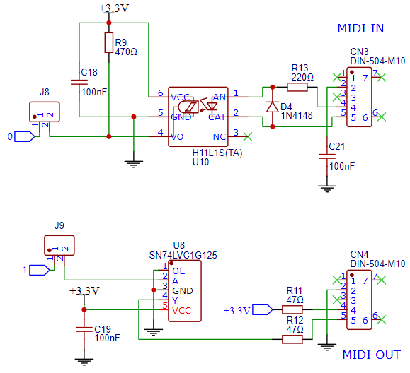
- Built-in MIDI IN/OUT connectors
- I2C1 brought out to breakout headers with 5V level shifted version also available
- SPI brought out to breakout headers
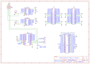
- Two SN74CBTLV3251 1 x 8 high-speed analog multiplexers allow connection of up to 16 analog or digital inputs
- MCP23017 16-channel I/O expander for connection of up to 16 digital latched inputs and outputs like switches and LEDs
- VBat connected to CR2032 battery holder
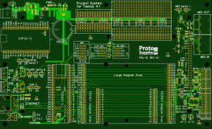
- Thru-hole breadboard style mounting area
- 3rd party module mounting area
- Adapter area for plugging in up to 2 standard Teensy adapter boards or a custom 4″ x 2.5″ large adapter board
- Male headers on Teensy 4.1 and ESP32-S for connecting breadboard jumpers or hooking up logic analyzer or O’scope probes.
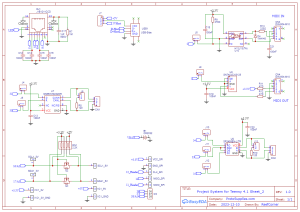
- DC-DC front-end for wide input voltage range of 6-16VDC
- 3.3V on-board regulator to off-load and protect the Teensy 3.3V regulator
- Input power setup supports DC input power and USB power to Teensy 4.1 and ESP32-S be applied at the same time.
- LCD does require external DC input power. If only USB power is applied, the baseboard will operate, but the LCD is automatically disconnected from the Teensy 4.1 via a logic bus switch.
- High quality 4-layer construction with ENIG (Electroless Nickel Immersion Gold) finish.
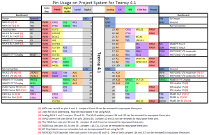
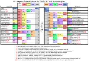
Baseboard Pin Usage
PDF and Excel formats of the above pinouts are available below:
Project System for Teensy 4.1 Pin Usage.pdf
Project System for Teensy 4.1 with Audio Pin Usage.pdf
Project System for Teensy 4.1 Pin Usage.xlsx
Continue reading below to learn about the features of the board as well as order options that can be used to complete your system.
Adapter Boards
The system can be further expanded by adding optional adapters. Note that not all adapters for the Prototyping System for Teensy 4.1 are completely compatible with this Project System baseboard or have limitations for use that are noted below.
The area next to the Teensy 4.1 is designed to provide flexibility for working with various adapters for adding functionality to the system. We offer a number of options below and it is fairly easy to design your own.
Small Adapter Boards
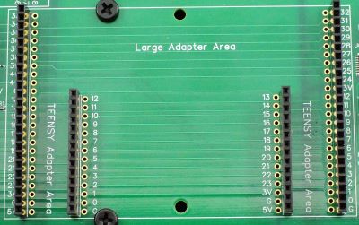
The area next to the Teensy 4.1 is footprinted to accept 2 of the standard size Teensy adapters such as the Audio Rev D adapter for easily working with them. These are labeled Teensy Adapter 1 & 2.
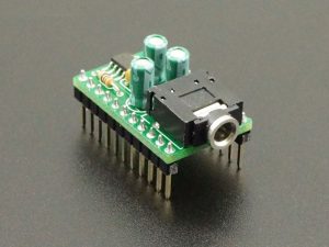
Teensy 4.x (Rev D) Audio Adapter (comes with Fully Stuffed version)
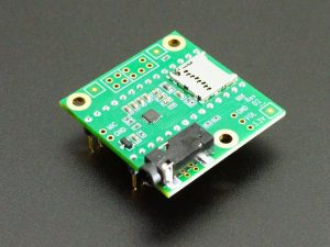
Because of the power of the Teensy 4.1, it is very popular for use with audio projects because it is fast enough to synthesize music on the fly and the PJRC team provides excellent tools like the PJRC Audio System Design Tool for working with their audio module. We have a version with pins preinstalled so it will plug into the baseboard. One comes installed in the Fully Stuffed version along with a 32GB SD card preloaded with sample WAV files.
The adapter is installed in the far right slot in the Fully Stuffed version to clear the standoff, but that standoff can be removed and the adapter moved to the left slot if desired.
For more product information click on the picture
PT8211 16-bit Stereo Audio Adapter for Teensy
The PT8211 is a low cost 16-bit stereo Digital-to-Analog (DAC) with line level output. It is supported by the PJRC Audio System Design Tool which makes it easy to use with the Teensy 4.1. We offer a version that is fully assembled with male header pins to make it plug-n-play with the baseboard. It is also available in kit form on the product page.
For more product information click on the picture
Large Adapters Boards
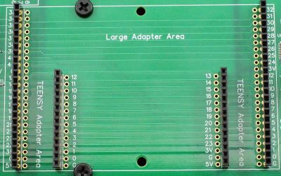
The same adapter area is also footprinted to accept a larger 4″ x 2.5″ adapter with access to all of the Teensy 4.1 pins available along the two edges of the PCB.
We offer adapter boards that plug in and allow permanent perf board or solderless breadboard circuits to be built that can be easily swapped in and out as desired without permanently modifying the main board. We also have a number of application specific adapter boards. This area also works well for custom boards that the user can design to add functionality for their specific setup.
Solderless Breadboard Adapter
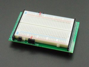
This adapter mounts a 400 tie-point high quality solderless breadboard for building temporary circuits.
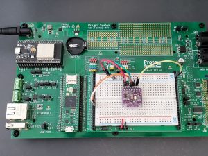
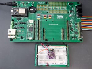
The female headers on either end of the breadboard provide access to all of the Teensy 4.1 pins. This allows circuits to be built, the whole baseboard assembly with solderless breadboard to be moved around and then the breadboard subassembly can be removed intact and replaced without having to reconnect anything. Works well for testing modules and circuits before permanently adding them to the baseboard.
The adapter allows 3.3V or 5V power to be selected for the power rails.
For more product information click on the picture
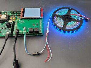
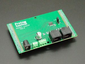
WS2812 Addressable LED Adapter
Important Note: This adapter can also be used with the Project System for Teensy 4.1 baseboard with the following caveats. Single channel output must be set for pin 24, and the MUX2 baseboard jumper J14(24) is removed. On the 8-channel RJ45 output, pin 5 conflicts with the LCD and cannot be used.
Teensy 4.1 and the Teensy products in general, are very popular for use with addressable LED projects because it is fast enough and has enough memory to do smooth animations of large numbers of LEDs.
We have created an adapter that makes it very easy to work with a string of addressable LEDs. Just plug in the LED strip and a 5V power source.
For more product information click on the picture
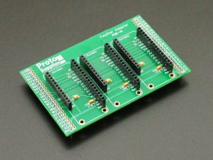
Adafruit Feather Adapter
Important Note: If considering using Adafruit Feather Adapter with this Project System baseboard, check the pins used by the Adafruit modules you are interested in using against the baseboard pin usage map to ensure there are no conflicts that can’t be resolved by removing unused jumpers on the baseboard.
If you are a fan of Adafruit, this adapter board mounts up to 3 Adafruit FeatherWings for working with them. Adafruit designs many unique products and creates many of the libraries and example software that make working with Arduino compatible boards possible.
For more product information click on the picture
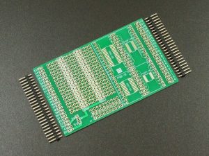
Thru-Hole and SMD Adapter
This adapter board is a general purpose solder type prototyping board with both thru-hole and 20-pin and 28-pin SOIC and TSSOP footprints which can fit smaller pin count ICs as well.
It allows permanent circuits to be built and easily plugged in and taken out of the baseboard.
For more product information click on the picture
Configuring System for Benchtop Development Use
To make the system easy to work with during development of your project, the Baseboard with LCD and Fully Stuffed versions that come with an LCD also ship with a 4″ male/female 40-pin extension cable and 4 longer M3 x 22mm standoffs. This allows the LCD to be removed from the baseboard and placed next to it for easy access to everything as shown below.
In this configuration, the system can be used as a general purpose prototyping setup similar to our Prototyping System for Teensy 4.1. We have tested using up to a 50cm (20″) long extender cable without noting any issues with the LCD, so it is possible to use a longer cable to relocate the LCD if desired.
Conversion steps
- Remove the screws in the 4 corners of the LCD and unplug it from the LCD connector on the baseboard.
- Screw in the 4 longer M3 x 22 standoffs that were provided in the package to serve as legs for the LCD.
- Remove the large M4 x 20 standoffs from the Teensy side of the baseboard and move them to the LCD side to serve as feet. You may want to leave off the one on the center right side where the extension cable will exit.
- Plug the male end of the extender cable into the female header on the baseboard oriented so that the cable exits the near side of the baseboard. Be sure to pay attention to the note below.
- Flip the baseboard so it is sitting on the standoffs and plug the female end of the extension cable onto the male pins on the bottom of the LCD.
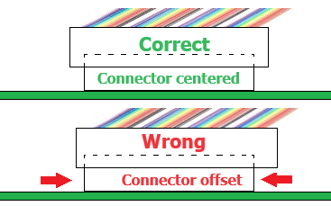
Important Note: When plugging the extension cable into the baseboard, ensure that the male cable connector is centered on the female connector with equal distance on both sides as it plugs in. It is possible to install the connector offset to one side or the other. This shorts out the power subsystem and the system will not operate and the green power LED will glow dimly. If this happens, remove power immediately and correct the cabling issue. In our testing, this has has not caused permanent damage.
Technical Details
Teensy 4.1 Support
The Teensy 4.1 socket brings all I/O out from the bottom of the Teensy 4.1. The socket also has a row of male headers for easily connecting logic analyzer or O’scope probes or for jumping pins over to a solderless breadboard or making temporary connections such as patching in the high-speed logic level converters.
We offer our Teensy 4.1 Fully Loaded for Prototyping System line of Teensy 4.1 products that are configured for use with this board and similar baseboard setups that bring the I/O down from the bottom of the Teensy 4.1. They include the following changes from the standard Teensy 4.1:
- The VUSB/VIN trace is cut and a 1A SMD Schottky diode is placed across the VUSB / VIN pads so both USB and VIN power can be safely applied at the same time.
- Optional PSRAM and/or Flash memory is added depending on configuration ordered.
- VUSB 1-pin header is installed for routing USB power to the baseboard.
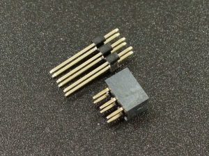
- A female 2×3 2mm header is mounted at the Ethernet connector location on the bottom side of the Teensy 4.1 which mates with an extended reach male header on the baseboard and connects the Teensy 4.1 to the MagJack on the baseboard.
- Male 5-pin headers are mounted to the bottom side of the Teensy 4.1 to bring down the USB Host lines to connect to the on-board Host USB connector. VBat connects to a CR2032 battery holder and On/Off and Program have no connections on this baseboard, but user can add if desired
- The standard 24-pin male I/O headers are installed
By separating the VUSB and VIN power inputs and placing a Schottky diode between them, this allows the Teensy 4.1 to be powered from both the USB cable and VIN input at the same time if the VIN power source also has a diode installed. It also allows the modified Teensy 4.1 to be powered on the bench from the USB cable without being placed into a baseboard which can be handy at times.
When used with a 3rd party baseboard, it removes the need to solder a diode onto the bottom of the Teensy 4.1. When used with our Project System for Teensy 4.1 baseboard, the Schottky diode on the Teensy 4.1 is in parallel with another one on the baseboard, so is redundant.
Power Subsystem
DC Input
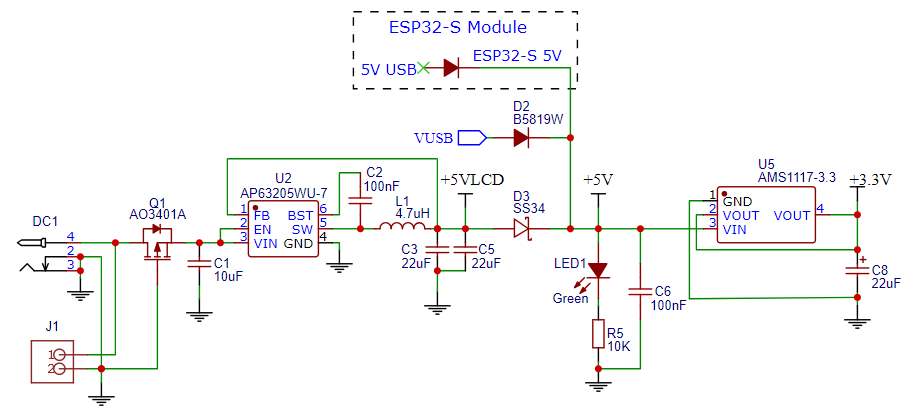
The board can be powered from 6 – 16VDC via a standard DC power jack.
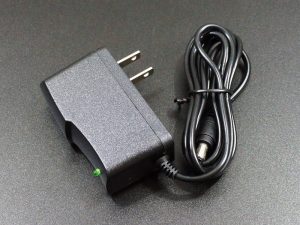
Our 7.5V 1A AC/DC converter works well with this board and one comes with the Fully Stuffed version. Any converter in the range of 6-16V with a 1A or greater current output and a standard 5.5mm x 2.1mm male plug will work OK.
For more product information click on the picture.
Besides the DC power jack, there is also a footprint labeled J1 for an optional 0.1″ 2-pin screw terminal or JST style connector for bringing in power or for powering an external device like a fan off the DC input.
Reverse voltage protection on the input is provided by a MOSFET transistor.
5V and 3.3V Subsystems
The DC input power feeds an AP63205 5V DC-DC converter U2. This 5V converter output is labeled +5VLCD and directly powers the LCD VDD pins. Important Note: The LCD has power only when DC power is connected to the power jack as the current draw is too much to safely draw only from USB power. The LCD also requires a full 5V to operate correctly.
This +5VLCD voltage along with any 5V power coming in from the USB connections on the Teensy 4.1 and/or the ESP32-S all pass through Schottky diodes to keep the different power subsytems safely isolated while powering the 5V bus on the baseboard. This allows any combination of USB and DC power to be connected. After the Schottky voltage drop, this results in approximately 4.7V on the 5V power rail. This is marginal for meeting the full 5V spec, but this works fine for most modules since they are regulating this input power down to 3.3V on their module anyway. If something requires the full 5V, there is an LCD 5V pad where this can be easily tapped into, but it will only have power when the DC input is connected.
This 5V power provides power to the Teensy 5V VIN input and the ESP32-S 5V input which all have their own built-in 3.3V regulators as well as provide 5V to the adapter area and breadboad areas. A power LED lights whenever 5V power is available.
The 5V power also feeds an AMS1117-3.3 linear regulator that powers the power rails that are labeled 3V or 3.3V on the board to take the load off the Teensy 4.1. This arrangement ensures that 3.3V is available no matter how the board is powered to avoid the possible issue of driving logic signals into an unpowered IC.
The Teensy 4.1 onboard 3.3V regulator output is not used on the baseboard, but the power is available on the 3.3V pins of the Teensy 4.1 socket. If these pins are used for any reason such as to supply power to a peripheral, be sure not to connect those Teensy 3.3V power pins to the on-board 3.3V or other power rails or damage could result. The same is true for the 3V3 pin of the ESP32-S.
Teensy 4.1 and Proto Adapter Area
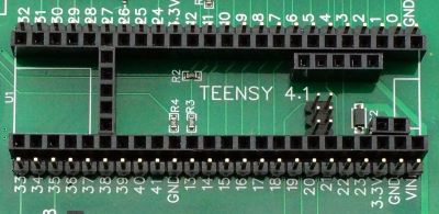
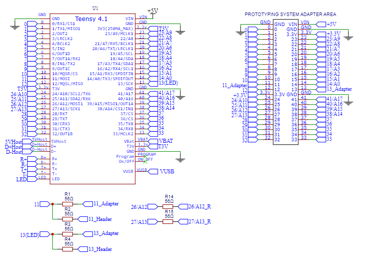
The entire Teensy 4.1 footprint is brought out to the proto adapter area. The outer 24-pin female headers support connecting to all of the Teensy 4.1 I/O pins and can fit a 4.0″ x 2.5″ adapter . The inner 14-pin headers support inserting up to two of the standard PJRC 14-pin adapter boards like the popular Teensy 4.x Rev D Audio Adapter.
The only electrical differences is that the SPI Clk pin 13 and MOSI pin 11 and SPI1 CLK pin 27 and MOSI pin 26 lines to the adapter area have 56Ω series resistors to minimize signal reflections. The 3V pins in the adapter area power are supplied from the baseboard 3.3V regulator and not from the Teensy 4.1.
Important note: The SPI1 bus is used to control the LCD on pins 26, 27 and 39. The LCD does not play nicely with other SPI devices on the same bus and so the user should not make use of this bus for other purposes. Other SPI devices should be controlled off the main SPI bus on pins 11, 12 and 13.
Capacitive Touch Display 7″ (Comes with Baseboard with LCD and Fully Stuffed versions)
The baseboard supports the BuyDisplay ER-TFTM070-5 7″ display with capacitive touch screen. It mounts on the opposite side of the PCB from the Teensy and other circuitry using a 2 x 20 female connector and 4 M3 x 11mm standoffs and screws.
For development purposes, the display can sit next to the baseboard using the 4″ extension cable for easier access. We tested with up to a 16″ extension cable without seeing any issues. When installing the male connector onto the female header on the baseboard, be sure that you have the connector centered with equal space on each side. It is easy to install it offset which causes the power subsystem to be shorted out. If you power on the system and the green power LED only glows weakly, that is your issue. In our testing this has fortunately not caused any permanent damage.
The LCD comes with the RA8875 display controller and the FT5206 touch controller. This display and touch controller are well supported by the Teensy 4.1 using the library RA8875.h which is built into the Teensyduino software and includes many example programs.
The LCD is connected to the SPI1 bus as it does not play nicely with other SPI devices, so examples will need to be modified slightly to use that bus. The code snippet below shows the how to properly configure the LCD to operate on the SPI1 bus on this baseboard.
// Pins used for LCD and touch.  Using SPI1 bus
const int RA8875_MISO = 39;
const int RA8875_MOSI = 26;
const int RA8875_SCLK = 27;
const int RA8875_CS = 5;
const int RA8875_RESET = 9;
const int RA8875_INT = 2;

// Setup LCD to use SPI1
RA8875 tft = RA8875(RA8875_CS, RA8875_RESET, RA8875_MOSI, RA8875_SCLK, RA8875_MISO);
The software supports both the display and touch screen through one interface. The touchscreen can support up to 5 simultaneous touches, recognizes gestures, automatically rotates to match the LCD rotation and requires no calibration of the touch points.
The display is connected to the SPI1 bus pins 26, 27, 39 with CS connected to pin 5 and /Reset connected to pin 9.
The touch connects to I2C pins 18 and 19 and the I2C address is hardwired to 0x38. The touch /IRQ output is brought int pin 2 on the Teensy 4.1.
LCD Power and Bus Control
As noted in the power section, the LCD has power only when the DC power input has power. This is done because the Baseboard with LCD draws close to 500mA which is the maximum allowed through USB. Adding additional circuitry can easily throw it over the limit. A secondary reason is that the LCD spec requires a voltage closer to 5v than the 4.7V on the system 5V power rail.
Since the USB can still be used to power the rest of the baseboard, precautions had to be made to electrically isolate the LCD when the baseboard is powered, but but the LCD is not, to avoid possible damage from driving unpowered inputs.
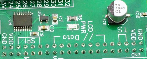
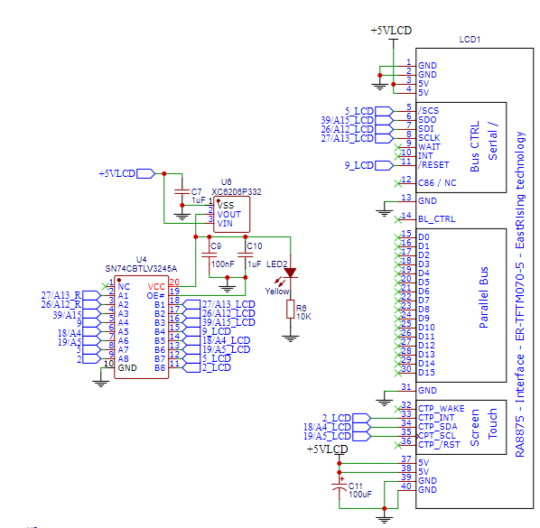
The +5VLCD that powers the LCD lights the yellow LCD PWR LED and also powers a small 3.3V regulator U6 that in turn powers an SN74CBTLV3245A FET bus switch U4. All of the signals going to and from the LCD pass through this bus switch.
If only USB power is applied, the rest of the baseboard will operate, but the LCD, if one is connected, will be unpowered. The unpowered bus switch in that case disconnects the signals going to/from the LCD to prevent possible damage from driving unpowered inputs. When DC input power is applied, the bus switch is activated and connects the LCD to the Teensy 4.1.
Note: An easy trap to fall into is if you have USB power applied to the baseboard and program the Teensy 4,1, but the LCD is left unpowered. If you then apply the DC input to power the LCD, it will not operate since the LCD did not get initialized since it was powered off when the Teensy tried to initialize it. In this case, you need to cycle power on the board or reprogram the Teensy 4.1 to restart the program.
Please Note: We optionally provide this LCD with the baseboard as a convenience to our customers that want to use the Project System without having to order an LCD from China. We do not sell the LCDs separately from the baseboard.
ESP32-S Co-Processor for WiFi / Bluetooth (Comes with Fully Stuffed version)
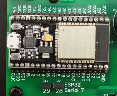
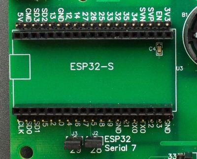
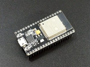
A socket is provided for an optional NodeMCU style ESP32-S development board. This is the 0.9″ wide 38-pin version that we sell and one comes with the Fully Stuffed option. There are many different flavors of ESP32 with different pin counts and pinouts, so check the pinout especially for power and ground if using one from a different source.
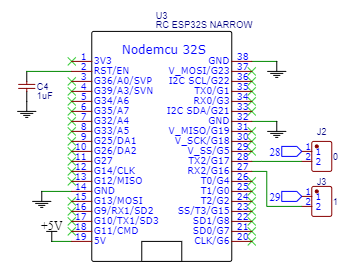
The Teensy 4.1 Serial7 on pins D28 and D29 connects to the ESP32-S Serial 2 on pins 28 and 27 to provide communications between the two microcontrollers.
The ESP32-S can be used as a co-processor to the Teensy 4.1 to offload all WiFi or Bluetooth work. The ESP32-S is much better suited for that type of work than the Teensy 4.1. It can also be used to offload other processing work such as to act as a dedicated sensor monitor or motor controller for instance to free the Teensy 4.1 up for other things.
A 1uF capacitor connects the RST/EN pin to ground. This allows software to be downloaded from the IDE without the need for pressing the IO0 (Boot) button.
The other pins on the ESP32-S are unallocated, so can be repurposed as desired. A row of adjacent male header pins is provided to make jumping over to a breadboard or the Teensy 4.1 easy, such as if you want to work with SPI instead of serial communications between the two microcontrollers.
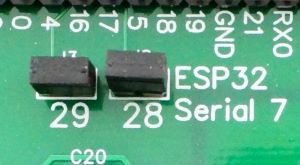
Two jumpers allow the Teensy 4.1 Serial 7 signals on pins 28 and 29 (28-RX, 29-TX) to be disconnected from the ESP32-S if it is desired to free up those pins on the Teensy 4.1 or if an alternate communication scheme such as SPI is being used with the ESP32.
For more product information click on the picture.
Wired Ethernet
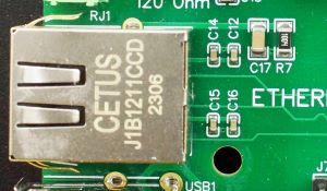
The board has a MagJack for making wired Ethernet connections. Teensy 4.1 has all the circuitry built-in for connecting to Ethernet and the two just need to be physically connected.
Note: Due to Ethernet PHY chip shortages and price increases, some Teensy 4.1 on the market are now being built without this chip and do not have Ethernet capability. All of the Teensy 4.1 we sell for this system have the PHY chip and full Ethernet capability, but if you plan to source or have already sourced a Teensy 4.1 from somewhere else for use with this board, keep that in mind if you plan to use Ethernet.
The baseboard has a extended length 2×3 2mm spacing male header to pickup the Ethernet connections from the bottom of the Teensy 4.1 that has a mating female header installed.
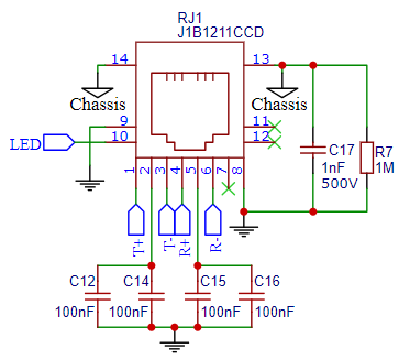
The Magjack shield is grounded via a 1MΩ resistor and high voltage 1nF capacitor.
See our Working with Ethernet for more information on using this feature.
USB Host
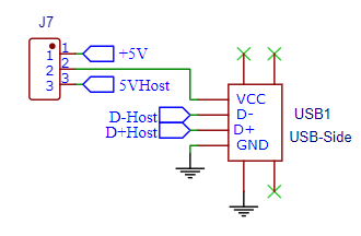
A 5-pin header under the Teensy 4.1 is used to pickup the USB Host lines. These are brought out to a side mounted USB 2.0 connector.
The USB Host is a 2nd USB port that allows you to connect USB devices to the Teensy 4.1. It is fully independent of the main USB device port, so USB devices can communicate simultaneously with Teensy while Teensy communicates with a computer via the USB device port. The USB Host port operates at up to 480Mbit/sec. Use the USBHost_t36 library for working with this port.
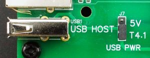
For providing power to the USB connector, there is a jumper USB 5V to select between using the standard switched USB 5V power from the Teensy 4.1 T4.1 or using the external VIN 5V unswitched power VIN which can be handy for powering higher current applications without having to resort to a powered hub.
Note that the T4.1 switched power is logically controlled by the Teensy 4.1, so a voltage won’t be present until it is enabled by the Teensy 4.1.
See our Working with USB Host for more infornation on using this feature.
MIDI
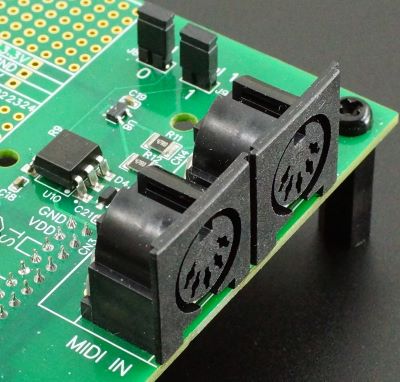
MIDI (Musical Instrument Digital Interface) is used to connect devices that make and control sound such as music synthesizers and keyboards by passing commands through the MIDI interface. MIDI does not transmit sounds such as .WAV files, but rather sends the information needed to reproduce the sound on the receiving equipment such as the note to play and the duration. The MIDI standard uses these 5-pin connectors. Some newer MIDI devices, especially low cost ones, now use MIDI over USB especially when connecting to a computer.
The MIDI interface is connected to Serial1 on the Teensy 4.1 and provides the physical and electrical interface between the Teensy 4.1 and external MIDI devices.
The input connector uses an H11L1 optoisolator to electrically protect the Teensy 4.1 from anything that may be misconnected or shorted on the input.
The output connector uses an SN74LVC1G125 buffer chip to electrically isolate the output connection from the Teensy 4.1 as well. It also provides additional drive current capability, though that typically isn’t required. The output connector by default loops-thru through any MIDI commands received on the input connector.
MIDI uses current for signaling rather than voltage, so resistors are used to set the signaling current to approximately 5mA when working with 3.3V logic.
Jumpers J8 and J9 allow Serial1 (pins 0/1) to be disconnected from the MIDI interface if it is desired to repurpose those lines or run the MIDI off a different serial port.
CAN Bus
CAN Bus is mainly used in automotive applications due to its distributed processing and robust communication protocol. It can also work quite well in other applications where multiple microcontrollers need to communicate over a common bus such as in robotics. Use the FlexCAN_T4 library for working with the CAN bus.
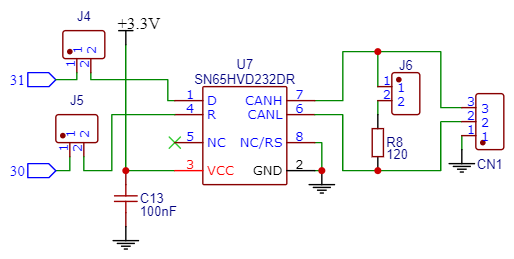
The Teensy 4.1 CAN3 bus on pins D30, D31 is connected to an SN65HVD230, 231 or 232 CAN bus transceiver. These parts are all equivalent parts in this circuit and selected based on availability.
Jumpers J4 (D31) and J5 (D30) allow those signals to be disconnected from the transciever chip if the pins are to be used for other purposes.
The output has a 120 ohm termination resistor which has a jumper J6 that can be removed to take the resistor out of circuit if needed for the application.
It connects to a 3-pin screw terminal CN1. Ground is typically not needed since the signal is differential, but is included in case it is desired to ground systems together.
RS485 Bus
RS485 is a long-line serial communication bus that allows multiple devices to connect to the same serial bus over long distances of up to 1200 meters. The underlying protocol is standard TTL level RS232 but with differential transceivers used to extend to long distances and support multiple device drops. Speeds of up to 2.5Mbit/sec are possible. Handy for device control of one or more devices over longer distances or in electrically noisy environments such as industrial control.
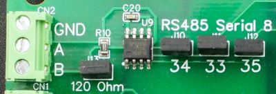
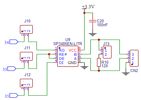
Serial8 on D34, D35 are connected to an SP3485E / RS485 transceiver chip. The direction control enable is connected to D33.
Jumpers J10 (D34), J11 (D33) and J12 (D35) allow those signals to be disconnected from the transceiver chhip if they will be used for other purposes.
The output has a 120 ohm termination resistor which has a jumper J13 that can be removed to take it out of circuit if needed for the application. For short benchtop type testing setups, the resistor may need to be removed on both ends.
The output comes out to a 3-pin screw terminal CN2. Ground is typically not needed since the signal is differential, but is included in case it is desired to ground systems together.
I/O Expansion
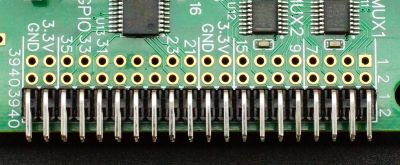
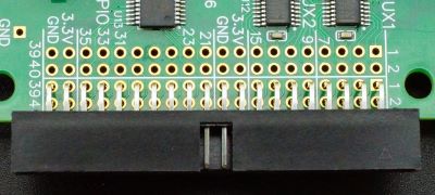
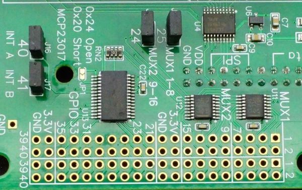
The baseboard incorporates two types of I/O expanders to provide up to 32 additional I/O lines that can be used either on the baseboard or off-board via a cable. The I/O comes out to a double set of 2×20 pads. A right-angle 2×20 header/connector can be installed as shown in the pictures for connecting to a ribbon cable. This connector can be placed on either side of the circuit board.
If only half of the I/O is being used a 2×10 connector can be used instead.
If using a vertical header instead of a right-angle, the space is too tight on the MUX1 side to use a ribbon cable connector unless there is no standoff in the adjacent hole. In that case an M4 nut can be used to secure the front acrylic standoff if used.
The I/O can also be picked-up from the other double row of solder pads if desired. This may be handy if using the extra I/O inside the Project System or if it is desired to pickup the I/O and route it to something such as a 3rd party module mounted on the baseboard.
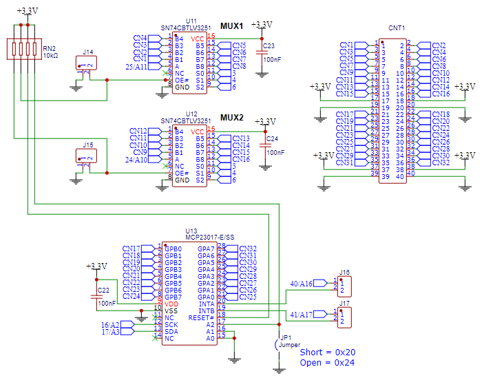
Two SN74CBTLV3251 1 x 8 FET multiplexer ICs U11 and U12 provide 16 of these I/O lines. Similar to the ubiquitous 4051/4067, these multiplexers are also bidirectional but have a much lower 5 ohm resistance and faster potential operating speed. They are useful for reading analog signals such as potentiometers or can be used to read digital signals including switches. They can also be used to output digital signals, but these signals are not latched so have limited practical use as outputs. The standard Mux.h library can be used for accessing these multiplexer chips.
The mux signals are connected to Teensy 4.1 pins D24/A10 and D25/A11 which can read analog or digital signals. Addressing is provided by pins D3, D4, D6 on both chips. This allows for faster operation since 2 inputs can be read after each address change if desired. If the mux chips are not being used, jumpers J14 and J15 on the enable inputs of the chips can be removed and the chip will go into a tristate mode. Those pins can then be repurposed.
An MCP23017 16-channel I2C digital I/O expander IC U13 can be used for input and/or output of digital signals and the outputs are latched. The IC sits on the I2C1 bus at address 0x24, but it can be changed to address 0x20 by shorting JP1 with solder. The MCP23017 supports one or two interrupt pins INTA / INTB that can optionally provide interrupts back to the Teensy 4.1 on pins D40 and D41 when input signals on the MCP23017 change state. The chip can also be polled in software. Any standard arduino library like Adafruit_MCP23X17.h can be used for controlling this IC. Jumpers J16 and J17 can be removed if one or both of these interrupt pins are to be repurposed.
I2C1 Bus
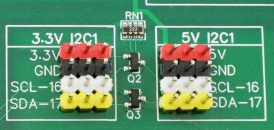
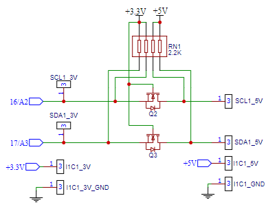
The I2C1 bus on pins D17, D16 is brought out to breakout headers along with 3.3V and ground. This bus is shared with the MCP23017 16-channel I2C digital I/O expander chip.
In addition, a 5V logic level shifted version of the I2C1 bus is also provided using the standard MOSFET setup and 2.2K pull-up resistors that will work for most applications. 5V and ground is provided for the logic level shifted versions.
The main I2C bus on pins D18 / D19 has the LCD touch controller on it and Audio Adapter if one is installed, but it can be tapped into as well if desired using jumper points on the baseboard.
SPI Bus
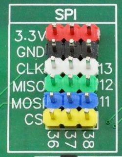
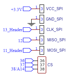
The main SPI bus on pins D11, D12 and D13 is brought out to three breakout headers along with 3.3V power and ground.
Three chip selects are connected to pins D36, D37 and D38. Those pins can be repurposed if not being used for SPI.
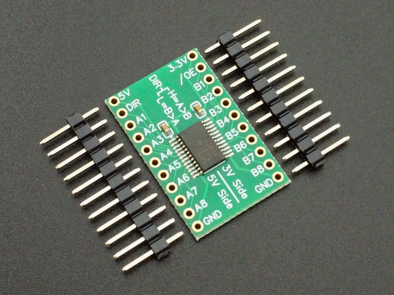
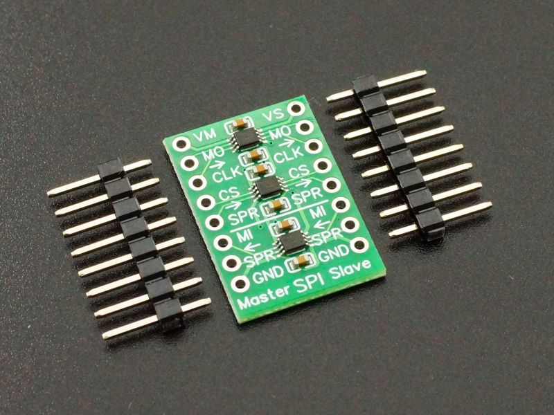
If a 5V version of SPI is needed, our high-speed SPI logic level shifter module can be mounted in the breadboard area.
The SPI bus is also routed to the adapter area of the board. CLK and MOSI each have two 56 ohm series resistors with the output of one branch going to the breakout header and the second branch going to the adapter area to minimize reflections on the bus.
Serial Ports
No serial ports are hardwired to dedicated headers on the baseboard, but headers can be mounted in the 3rd party module mounting area and wired up if needed.
The serial port usage on the baseboard is as follows:
- Serial 1 – is used for MIDI, but can be repurposed by removing J8, J9
- Serial 2 – pins are unused unless the Audio Adapter is installed
- Serial 3 – is unused
- Serial 4 – pins are used for I2C1 on the baseboard and has 2.2K pullups and used for MCP23017 control
- Serial 5 – pins are unused unless the Audio Adapter is installed
- Serial 6 – pins are used by MUX 1 and MUX 2, but can be repurposed by removing J14, J15
- Serial 7 – is connected to the ESP32-S for communication if installed but can be repurposed by removing J5, J6
- Serial 8 – is connected to the RS485 transciever, but can be repurposed by removing J10, J12
MISC Stuff
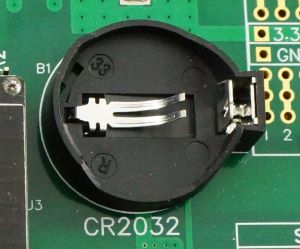
A CR2032 coin cell batter holder connects to the VBat on the Teensy 4.1 for providing battery backup capability.
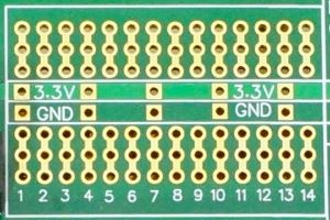
There is a small breadboard area that can mount up to a 28-pin IC or adapter. 3.3V and ground rails are provided for easy power hook-up.
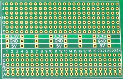
There is a perf board area that is provided mainly for mounting 3rd party modules that can then be wired into the system. The bottom two rows A-A are tied together. This allows a male header to be soldered in the bottom row and a female header in the row above it. The module plugs into the female header and the male header can be used to jumper signals to the module during system integration. The jumps can then be replaced with permanently soldered wires once the setup is working if desired.
3.3V, 5V and ground rails are provided for easy power hookup.
Designing Your Own Adapter
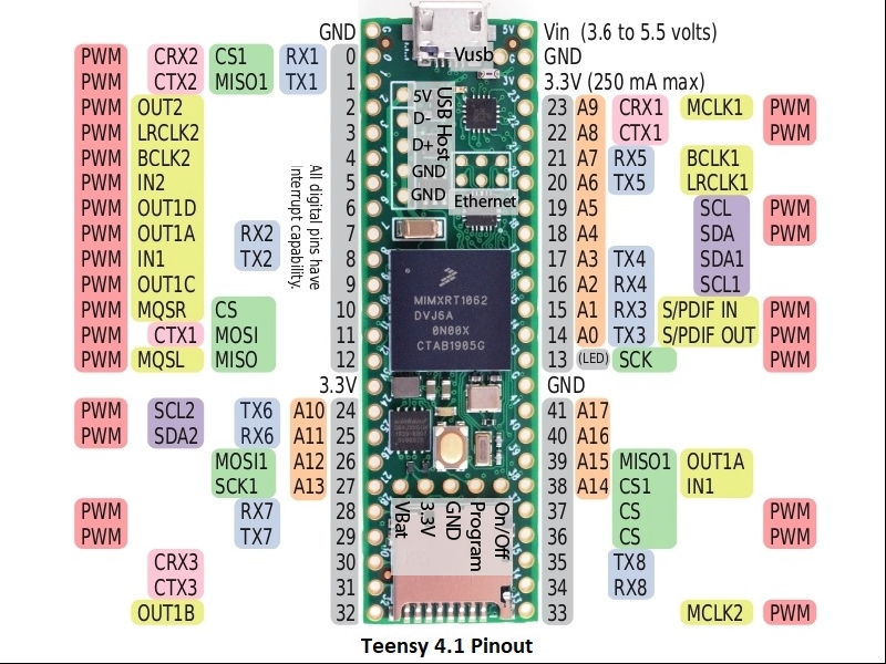
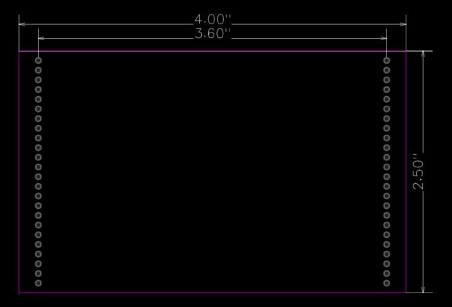
Since designing basic PCBs through quick-turn houses is fairly easy these days, this feature allows users to design and build application specific circuits to add functionality to the Project System. The adapter footprint is simply a 3.6″ wide Teensy 4.1 pinout as shown below.
A custom PCB height greater than 2.5″ (up to 5″) can also be used if the overhang is on the back edge of the board if it doesn’t conflict with the breakout headers (which could be cut off if needed) or user added modules.
Modifying An Existing Teensy 4.1 For Use With This Baseboard
If you already have a Teensy 4.1 that you want to use with this baseboard, it is fairly easy to adapt to it with nominal thru-hole soldering skills and a sharp knife by following the directions below.
If you ordered the Fully Stuffed version and want to verify the basic setup works before modifying your Teensy 4.1, you can download the program into the unmodified Teensy and then install it into the Teensy 4.1 socket. The ESP32-S will already be programmed. Connect power to the DC Power Input and the setup should run. Please Note: It is important to not also apply power through USB until the Teensy 4.1 has been modified as follows or damage could result.
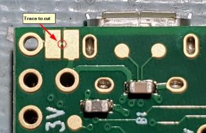
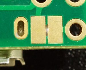
- Cut the trace between the pads on the bottom of the Teensy 4.1 to isolate the USB power from VIN power. Use a sharp X-acto knife or box knife with a new blade. Angle the blade at about a 45 degree angle and press straight into the trace on one side. Don’t use a sawing motion as you are just cutting through soft copper. Move the blade to the other side of the trace and repeat the process to remove a small wedge of the trace. A magnifier definitely makes this process easier if you have access to one. A properly cut trace is shown at the bottom. If you have a ohm meter, use it to verify the cut was successful by measuring across the pads. You should not measure a dead short.
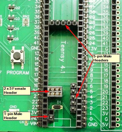
- Place male headers into the 5 pin Host USB and 5-pin VBat female headers on the baseboard. The picture is of a different board, but the concept is the same.
- Place a single male header pin in the front VUSB position of the 2-pin female header on the baseboard.
- Install a female 2×3 2mm header on top of the tall 2×3 2mm male header if your Teensy does not already have a male header in that location. Push it just slightly onto the male header, so you can align the pins with holes in the Teensy 4.1 first as you install the Teensy 4.1.
- Install the Teensy 4.1 into its socket making sure that the pins of the headers you just installed all line up with the holes in the Teensy 4.1 and protrude through. It doesn’t hurt to give a light tug on a couple of the 2×3 2mm female header pins to make sure it is seated firmly up against the bottom of the Teensy 4.1.
- Solder the headers in place. This ensures everything lines up properly.
The baseboard includes the necessary diode, D1 in the picture above but D2 on this board, so no Schottky diode needs to be added to the Teensy 4.1.
Using The Project System For Teensy 4.1
Note: We are creating a Tutorial section to help capture and better organize more information on using this Project System and the Prototyping System than can be put into a product pages. This includes a more detailed explanation of the preloaded example software shown below. Some of the tutorials overlap with the Prototyping System since some features are almost identical.
The setup described in this section illustrates the basic usage of some of the core parts of the system and provides a starting point for anyone just getting started with the Teensy 4.1 ecosystem. It also helps to jumpstart using the touch LCD since the RA8875 is not as widely used compared to something more common like the ILI9341. It assumes that at least an LCD is installed and also looks to see if an ESP32-S and Teensy 4.x Rev D Audio adapter board with SD card are also installed to enable additional functionality.
Important Note: When first using the RA8875 library, you will need to tell it that it is using a Capacitive Touchscreen instead of a Resistive Touchscreen which is the default. To do that, locate the RA8875UserSetting.h file. On a PC, it may be located at: “C:\Program Files(x86)\Arduino\hardware\teensy\avr\libraries\RA8875\_settings\RA8875UserSettings.h” or do a drive search for the file name.
Open the file and comment out the #define USE_RA8875_TOUCH and uncomment the #define USE_FT5206_TOUCH. It should look as shown below, then save the file.
/* [CHOOSE YOUR TOUCH SCREEN TYPE] +++++++++++++++++++++++++++++++++++++++++++++++++++++++++++++++
This library supports the RA8875 internal resistive touch screen driver or a FT5206
based capacitive touch screen driver. Below, you have to choose one of them.
The Resistive Touch screen it’s drived directly by RA8875.
The Capacitive Touch Screen use a I2C chip called FT5206 (hardwired to address 0x38).
Please choose at list one (NOT both), if you comment both it’s the same as _AVOID_TOUCHSCREEN*/
//#define USE_RA8875_TOUCH//resistive touch screen
#define USE_FT5206_TOUCH//capacitive touch screen
If you ordered the Fully Stuffed version along with a Teensy 4.1, it will already be loaded with the software below and will run as soon as power is applied. If you ordered a Fully Stuffed version without the Teensy 4.1, you will just need to load the software into the Teensy 4.1 as everything else will be setup.
The programs are not overly clever on the programming to make them easier to follow and pull heavily from various example programs. The communications between the Teensy 4.1 and ESP32-S in particular are handled in a very simplistic fashion by passing simple text strings.
There are two programs below. One is for the Teensy 4.1 and the second is for the ESP32-S if one is installed. Here is an overview of the programs.
Teensy 4.1 Program Overview
- Configures the serial ports and LCD/touch screen
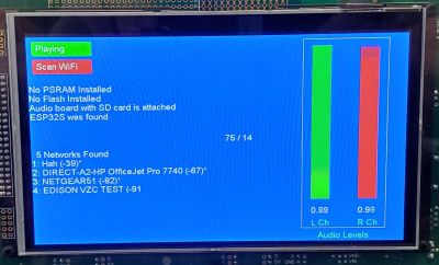
- Checks to see if any of the PSRAM or Flash memory chips have been installed on the Teensy 4.1 and reports that info out the serial port and also prints it on the LCD. If you ordered a system with the Teensy 4.1 already installed, this also provides a way to verify that you received the correct version without having to pry the Teensy 4.1 out of its socket.
- Paints three of buttons on the LCD screen. One for playing audio, one for scanning for WiFi networks, one for reading the I/O expander chips.
- Implements a simple serial communication path with the ESP32-S to see if one is attached. First asking if one is out there by sending a ‘?’ and looking for a ‘Y’ yes in return. If found, it enables the WiFi Scan button. If a scan is requested, it sends the command ‘S’ for scan to the ESP32-S and then looks for a response back with the found networks. The found networks are then listed on the bottom half of the LCD.
- It also looks for an Audio adapter with an SD card in it with the SDTEST2.WAV file on it (found at https://www.pjrc.com/teensy/td_libs_AudioDataFiles.html.) If found, it draws a L/R channel amplitude box and it enables the Play Audio button to allow the audio to be started and stopped. These files are included on the SD card with the Fully Stuffed version.
- If the I/O Scan button is selected, it reads the two 8-bit MUX chips as analog inputs and the 16-bit MCP23017 I2C digital I/O expander chip and displays the results in the bottom half of the LCD. The MUX chip inputs will be floating and usually read about 500, but can be temporarily grounded or connected to 3.3V using a jumper to see the effect when the button is pressed. The MCP23017 is configured as an input device with pullups so it will read all 1’s. If a pin is grounded using a jumper, it will read a 0 on that pin.
- It reports all touch coordinates in the center of the screen and sends button hits and misc info out to the USB port for display in a Serial Monitor window if one is open.
ESP32-S Program Overview
- Looks for incoming serial commands.
- If it gets a command ‘?’, it responds with ‘Y’ to let the Teensy 4.1 know that yes, it is there.
- If it gets a command ‘S’, it scans for networks and reports the results back to the Teensy 4.1
- It also reports the scan information out the USB port for display in a Serial Monitor window if one is open.
- This program is based largely on the WiFiScan example program.
If the ESP32-S is installed and you have two USB cables, you can open two instances of the IDE with one connected to the Teensy 4.1 and one connected to the ESP32-S for downloading the programs and Serial Monitor windows can be opened on both to see what is going on. This makes it easy to make program changes to either processor and download new code without messing with cables. To open 2 separate instances of the IDE, they both need to be launched by clicking on the application icon.
Teensy 4.1 Demo Example
/*
  Project System for Teensy 4.1 Example

  This program checks for presence of PSRAM/Flash memory, the Audio adapter
  with SD card and the ESP32.  Sends the results to the LCD and serial port and
  then draws 3 buttons on the LCD screen - Audio, WiFi Scan abd I/O Scan

  If Audio adapter is attached with an SD card installed, the Audio
  button plays the wave file "SDTEST2.WAV" from the Teensy audio tutorial
  https://www.pjrc.com/teensy/td_libs_AudioDataFiles.html
  It also displays a peak meter for the left/ right audio channels on the
  right side of the display.

  The WiFi Scan button sends a command to the ESP32S requesting a scan of
  available WiFi networks.  When the ESP32S returns the scan results,
  the Teensy 4.1 updates those results on the LCD screen and serial port.
  This requires an ESP32S to be installed and the sample program
  ESP32_Teensy_41_Demo be loaded on it, which is just a modified version
  of the ESP32 WiFiScan example program.

  To work with the Capacitive touch, edit RS8875UserSettings.h to enable touch.
  Comment out resistive touch and uncomment capacitive touch as shown here
    //#define USE_RA8875_TOUCH//resistive touch screen
    #define USE_FT5206_TOUCH//capacitive touch screen

  File may be found at this location on Windows or do a search for it on the harddrive:
  "C:\Program Files(x86)\Arduino\hardware\teensy\avr\libraries\RA8875\_settings\RA8875UserSettings.h"

  Download https://github.com/stechio/arduino-ad-mux-lib for working with the analog/digital
  multiplexers

  Download https://github.com/adafruit/Adafruit-MCP23017-Arduino-Library for working
 with the  MCP23017 I/O Expander

  Download https://github.com/mjs513/ILI9341_fonts and unzip into Arduino/Library folder
  to use fonts other than the standard that come with this LCD which are not very good.

  This example code is in the public domain.
*/

#include <Audio.h>
#include <Wire.h>
#include <SPI.h>
#include <SerialFlash.h>
#include <RA8875.h>
#include <SD.h>
#include <LittleFS.h>
#include <Mux.h>
#include <Adafruit_MCP23X17.h>
#include <font_Arial.h>
extern "C" uint8_t external_psram_size;

using namespace admux;
Adafruit_MCP23X17 mcp;

// This section comes from the Teensy Audio Design Tool
AudioPlaySdWav playSdWav1;
AudioAnalyzePeak peak2;
AudioAnalyzePeak peak1;
AudioOutputI2S i2s1;
AudioConnection patchCord1(playSdWav1, 0, i2s1, 0);
AudioConnection patchCord2(playSdWav1, 0, peak1, 0);
AudioConnection patchCord3(playSdWav1, 1, i2s1, 1);
AudioConnection patchCord4(playSdWav1, 1, peak2, 0);
AudioControlSGTL5000 sgtl5000_1;

// Pins used with the Teensy Audio Shield
const int SDCARD_CS_PIN = 10;
const int SDCARD_MOSI_PIN = 11;
const int SDCARD_SCK_PIN = 13;

// Pins used for LCD and touch.  Using SPI1 bus
const int RA8875_MISO = 39;
const int RA8875_MOSI = 26;
const int RA8875_SCLK = 27;
const int RA8875_CS = 5;
const int RA8875_RESET = 9;
const int RA8875_INT = 2;

// Setup LCD to use SPI1
RA8875 tft = RA8875(RA8875_CS, RA8875_RESET, RA8875_MOSI, RA8875_SCLK, RA8875_MISO);

const int MAXTOUCHLIMIT = 1;  // (1 to 5) number of simultaneous touches allowed
const int DARKGRAY = 0x29A7;
const int TOUCH_CHECK_INTERVAL = 20;  //msec

// Define Audio button location and size
const int AUDIO_X = 10;
const int AUDIO_Y = 10;
const int AUDIO_W = 125;
const int AUDIO_H = 32;

// Define Scan button location and size
const int SCAN_X = 10;
const int SCAN_Y = 60;
const int SCAN_W = 125;
const int SCAN_H = 32;

// Define I/O Expansion button location and size
const int IO_X = 175;
const int IO_Y = 10;
const int IO_W = 125;
const int IO_H = 32;

// Define Left Audio Channel location and size
const int LEFT_X = 620;
const int LEFT_Y = 380;
const int LEFT_W = 40;
const int LEFT_H = 360;

// Define Right Audio Channel location and size
const int RIGHT_X = 720;
const int RIGHT_Y = 380;
const int RIGHT_W = 40;
const int RIGHT_H = 360;

#define ESP32SERIAL Serial7  // ESP32 is attached to Serial7 port

uint16_t coordinates[MAXTOUCHLIMIT][2];  //to hold touch coordinates
uint16_t lastpX = 0;
uint16_t lastpY = 0;
const uint16_t maxRadius = 5;
bool touchReported = false;
bool releaseReported = false;
elapsedMillis touchTimer = 0;

// Subroutine prototypes
void SetWiFiScanButton(boolean);  // Handles Scan button when touched
void SetAudioButton(boolean);     // Handles Audio button when touched
void SetIOScanButton(boolean);    // Handles I/O button when touched
void UpdateAudioLevels();         // Updates audio level meter

// Creates two 8-channel Mux instances with same address pins.
Mux mux1(Pinset(3, 4, 6));
Mux mux2(Pinset(3, 4, 6));

// Misc flags to keep track of things
boolean WiFi_ScanRequested = false;    // Flag if WiFi scan is in process
boolean IO_ScanRequested = false;      // Flag if I/O scan is in process
boolean audioAdapterAttached = false;  // Flag if audio bd with SD card attached
boolean audioPlaying = false;          // Flag if audio is currently playing
boolean audioUpdatePause = false;      // Flag to temporarily pause audio
boolean esp32SAttached = false;        // Flag if ESP32S is attached

// Setup timer for audio levels graph updates.
elapsedMillis msecs;
//===============================================================================
//  Initialization
//===============================================================================
void setup() {
  Serial.begin(115200);       //Initialize USB serial port to computer
  ESP32SERIAL.begin(115200);  //Initialize Seria17 connected to ESP32S Serial2

  // Setup LCD screen
  tft.begin(RA8875_800x480);
  tft.setRotation(2);   // Rotates both screen and touchscreen
  tft.brightness(255);  // Set brightness to max (default)
#if defined(USE_FT5206_TOUCH)
  tft.useCapINT(RA8875_INT);         //We use the capacitive chip Interrupt out
  tft.setTouchLimit(MAXTOUCHLIMIT);  // Set max touches we will recognize
  tft.enableCapISR(true);            //Arm capacitive touch screen interrupt
#else                                // First time use - edit this file to enable touch
  tft.print("you should open RA8875UserSettings.h file and uncomment USE_FT5206_TOUCH!");
#endif
  tft.fillWindow(RA8875_BLUE);     // Fill window blue
  tft.setTextColor(RA8875_WHITE);  // White text, transparent background
  tft.setCursor(1, 110);           // Set initial cursor position
  //tft.setFontScale(0);           // If using the built-in fonts
  tft.setFont(Arial_14);  // If using custom fonts like we are here

  // Check for PSRAM chip(s) installed
  uint8_t size = external_psram_size;
  if (size == 0) {
    Serial.println("No PSRAM Installed");
    tft.println("No PSRAM Installed");
  } else {
    Serial.printf("PSRAM Memory Size = %d Mbyte\n", size);
    tft.printf("PSRAM Memory Size = %d Mbyte\n", size);
    tft.println();
  }

  LittleFS_QSPIFlash myfs_NOR;  // NOR FLASH
  LittleFS_QPINAND myfs_NAND;   // NAND FLASH

  // Check for NOR Flash chip installed
  if (myfs_NOR.begin()) {
    Serial.printf("NOR Flash Memory Size = %d Mbyte / ", myfs_NOR.totalSize() / 1048576);
    Serial.printf("%d Mbit\n", myfs_NOR.totalSize() / 131072);
    tft.printf("NOR Flash Memory Size = %d Mbyte / ", myfs_NOR.totalSize() / 1048576);
    tft.printf("%d Mbit\n", myfs_NOR.totalSize() / 131072);
  }
  // Check for NAND Flash chip installed
  else if (myfs_NAND.begin()) {
    Serial.printf("NAND Flash Memory Size =  %d bytes / ", myfs_NAND.totalSize());
    Serial.printf("%d Mbyte / ", myfs_NAND.totalSize() / 1048576);
    Serial.printf("%d Gbit\n", myfs_NAND.totalSize() * 8 / 1000000000);
    tft.println("NAND Flash Memory Size = ");
    tft.printf("%d bytes / ", myfs_NAND.totalSize());
    tft.printf("%d Mbyte / ", myfs_NAND.totalSize() / 1048576);
    tft.printf("%d Gbit\n", myfs_NAND.totalSize() * 8 / 1000000000);
  } else {
    Serial.printf("No Flash Installed\n");
    tft.printf("No Flash Installed\n");
  }
  tft.println();

  // Check for Audio bd with SD card installed
  if (!(SD.begin(SDCARD_CS_PIN))) {
    Serial.println("Audio board with SD card not found");
    tft.println("Audio board with SD card not found");
    audioAdapterAttached = false;
  } else {
    Serial.println("Audio board with SD card is attached");
    tft.println("Audio board with SD card is attached");
    audioAdapterAttached = true;
  }

  // Check for ESP32 installed
  ESP32SERIAL.print("?");         // Ask ESP32 if it is there
  delay(100);                     // Wait a bit for ESP32 to respond
  if (ESP32SERIAL.available()) {  // If there is a response
    String returnData = ESP32SERIAL.readString();
    if (returnData == 'Y') {  // ESP32S responded with Y for Yes, I'm here
      esp32SAttached = true;
      Serial.println("ESP32S was found");
      tft.println("ESP32S was found");
    } else {  // Invalid response
      Serial.println("ESP32S invalid response");
      tft.println("ESP32S invalid response");
      esp32SAttached = false;
    }
  } else {  // ESP32S did not respond
    Serial.println("ESP32S not found");
    tft.println("ESP32S not found");
    esp32SAttached = false;
  }

  // Draw initial buttons
  SetAudioButton(false);
  SetWiFiScanButton(false);
  SetIOScanButton(false);

  // Setup audio
  if (audioAdapterAttached) {  // Setup the audio if found
    AudioMemory(8);
    sgtl5000_1.enable();
    sgtl5000_1.volume(0.5);
    SPI.setMOSI(SDCARD_MOSI_PIN);
    SPI.setSCK(SDCARD_SCK_PIN);
    tft.drawRect(600, 10, 180, 440, RA8875_YELLOW);
    tft.setTextColor(RA8875_GREEN);
    tft.setCursor(635, 460);
    tft.print("Audio Levels");
    tft.setCursor(LEFT_X, LEFT_Y + 50);
    tft.print("L Ch");
    tft.setCursor(RIGHT_X, RIGHT_Y + 50);
    tft.print("R Ch");
    tft.setTextColor(RA8875_WHITE);
  } else {  // If no audio, gray out button
    tft.setCursor(AUDIO_X + 8, AUDIO_Y + 8);
    tft.setTextColor(RA8875_WHITE);
    tft.fillRoundRect(AUDIO_X, AUDIO_Y, AUDIO_W, AUDIO_H, 4, DARKGRAY);
    tft.print("No Audio");
  }

  // Setup ESP32
  if (!esp32SAttached) {  // If no ESP32 gray out button
    tft.setCursor(SCAN_X + 8, SCAN_Y + 8);
    tft.setTextColor(RA8875_WHITE);
    tft.fillRoundRect(SCAN_X, SCAN_Y, SCAN_W, SCAN_H, 4, DARKGRAY);
    tft.print("No Scan");
  }

  // Setup I/O Scan
  tft.setCursor(IO_X + 8, IO_Y + 8);
  tft.setTextColor(RA8875_WHITE);
  tft.fillRoundRect(IO_X, IO_Y, IO_W, IO_H, 4, RA8875_RED);
  tft.print("I/O Scan");
  // Setup for either digital or analog input
  //mux1.signalPin(24, INPUT, PinType::Digital);
  mux1.signalPin(25, INPUT, PinType::Analog);
  mux2.signalPin(24, INPUT, PinType::Analog);
  // Intialize MCP23017 and configure all pins as inputs
  if (!mcp.begin_I2C(0x24, &Wire1)) Serial.println("MCP23017 Error.");
  for (int i = 0; i < 16; i++) {
    mcp.pinMode(i, INPUT_PULLUP);
  }
}
//===============================================================================
//  Main
//===============================================================================
void loop() {
  // Keep an eye on any audio that may be playing and reset button when it ends
  if (playSdWav1.isStopped() && audioPlaying) {  // Audio finished playing
    SetAudioButton(false);
    Serial.println("Audio finished playing");
  }
  if (tft.touched()) {                  // Check for LCD touch
    tft.updateTS();                     // update data inside library
    tft.getTScoordinates(coordinates);  // Get touch coordinates in pixels
    uint16_t pX = coordinates[0][0];
    uint16_t pY = coordinates[0][1];
    tft.setTextColor(RA8875_WHITE, RA8875_BLUE);
    tft.setCursor(CENTER, CENTER);  // print touch coordinates in center of screen
    tft.print(pX);
    tft.print(" / ");
    tft.print(pY);
    tft.print("                  ");  // Erase any extra left over characters
    // Ignore if touching same spot
    if ((pX != lastpX) || (pY != lastpY)) {
      lastpX = pX;
      lastpY = pY;
      // Look for an Audio Button Hit
      if ((pX >= AUDIO_X) && (pX <= (AUDIO_X + AUDIO_W))) {
        if ((pY >= AUDIO_Y) && (pY <= (AUDIO_Y + AUDIO_H))) {
          Serial.println("Audio Button Hit");
          if (audioAdapterAttached && !audioPlaying) {
            SetAudioButton(true);
          } else if (audioAdapterAttached && audioPlaying) {
            SetAudioButton(false);
          }
        }
      }
      // Look for a WiFi Scan Button Hit
      if ((pX >= SCAN_X) && (pX <= (SCAN_X + SCAN_W))) {
        if ((pY >= SCAN_Y) && (pY <= (SCAN_Y + SCAN_H))) {
          Serial.println("Scan Button Hit");
          if (esp32SAttached) SetWiFiScanButton(true);
        }
      }

      // Look for I/O Scan Button Hit
      if ((pX >= IO_X) && (pX <= (IO_X + IO_W))) {
        if ((pY >= IO_Y) && (pY <= (IO_Y + IO_H))) {
          IO_ScanRequested = true;  // Flag if I/O scan is in process
          Serial.println("IO Scan Button Hit");
          SetIOScanButton(true);
        }
      }
    }
  }
  // If we requested a WiFi scan, look for serial data coming from the ESP32S
  if (WiFi_ScanRequested && ESP32SERIAL.available()) {
    audioUpdatePause = true;  // Pause any audio level updates if audio playing
    Serial.println("Read incoming data");
    tft.fillRect(0, 260, 595, 220, RA8875_BLUE);  // Clear any previous text
    tft.setCursor(10, 280);
    while (ESP32SERIAL.available()) {  // Print the scan data to the LCD & USB
      String returnData = ESP32SERIAL.readString();
      tft.println(returnData);
      Serial.println(returnData);
    }
    SetWiFiScanButton(false);
    audioUpdatePause = false;
  }

  // Update audio levels every 30 milliseconds if audio is playing
  if ((msecs > 30) && audioPlaying && !audioUpdatePause) UpdateAudioLevels();
}
//===============================================================================
//  Routine to draw Audio button current state and control audio playback
//===============================================================================
void SetAudioButton(boolean audio) {
  tft.setCursor(AUDIO_X + 8, AUDIO_Y + 8);
  tft.setTextColor(RA8875_WHITE);

  if (!audio) {  // button is set inactive, redraw button inactive
    tft.fillRoundRect(AUDIO_X, AUDIO_Y, AUDIO_W, AUDIO_H, 4, RA8875_RED);
    tft.print("Play Audio");
    audioPlaying = false;
    if (audioAdapterAttached) {
      // Clear audio level info
      tft.fillRect(LEFT_X, LEFT_Y - LEFT_H, LEFT_W, LEFT_H, RA8875_BLUE);
      tft.fillRect(RIGHT_X, RIGHT_Y - RIGHT_H, RIGHT_W, RIGHT_H, RA8875_BLUE);
      tft.setTextColor(RA8875_WHITE, RA8875_BLUE);
      tft.setCursor(LEFT_X, LEFT_Y + 20);
      tft.print("0.00");
      tft.setCursor(RIGHT_X, RIGHT_Y + 20);
      tft.print("0.00");
    }
    if (playSdWav1.isPlaying()) {  // Stop any audio that is playing
      playSdWav1.stop();
      Serial.println("Audio being stopped");
    }
  } else {  // button is active, redraw button active
    tft.fillRoundRect(AUDIO_X, AUDIO_Y, AUDIO_W, AUDIO_H, 4, RA8875_GREEN);
    tft.print("Playing");
    audioPlaying = true;
    if (audioAdapterAttached && !playSdWav1.isPlaying()) {  // Play audio file
      Serial.println("Audio being played");
      playSdWav1.play("SDTEST2.WAV");
      delay(10);  // wait for library to parse WAV info
    }
  }
  delay(500);  // Minimize double-hits on Audio button
}
//===============================================================================
//  Routine to draw WiFi scan button current state and initiate scan request
//===============================================================================
void SetWiFiScanButton(boolean scanning) {
  tft.setCursor(SCAN_X + 8, SCAN_Y + 8);
  tft.setTextColor(RA8875_WHITE);

  if (!scanning) {  // Redraw button inactive
    tft.fillRoundRect(SCAN_X, SCAN_Y, SCAN_W, SCAN_H, 4, RA8875_RED);
    tft.print("Scan WiFi");
    WiFi_ScanRequested = false;  // Reset the scan flag
  } else {                       // Button is active, redraw button active
    tft.fillRoundRect(SCAN_X, SCAN_Y, SCAN_W, SCAN_H, 4, RA8875_GREEN);
    tft.print("Scanning");
    ESP32SERIAL.println("S");   // Send command to ESP32 to start scan
    WiFi_ScanRequested = true;  // Set flag that we requested scan
    Serial.println("Scan being requested");
  }
}
//===============================================================================
//  Routine to update I/O scan button state and do I/O scan
//===============================================================================
void SetIOScanButton(boolean scanning) {
  int data;
  if (scanning) {
    tft.setCursor(IO_X + 8, IO_Y + 8);
    tft.setTextColor(RA8875_WHITE);
    tft.fillRoundRect(IO_X, IO_Y, IO_W, IO_H, 4, RA8875_GREEN);
    tft.print("I/O Scanning");
    tft.fillRect(0, 260, 595, 220, RA8875_BLUE);  // Clear any previous text
    tft.setCursor(0, 280);
    // Read MUX 1 pins.  These were setup as analog inputs so will read
    // floating values of around 500 unless connected to a voltage source
    // like a pot or 3V or GND
    tft.print("MUX1 Analog Data = ");
    Serial.println("I/O Scan");
    Serial.println("MUX 1 Analog Data");
    for (int i = 0; i < 8; i++) {  // Read all MUX 1 inputs
      mux1.channel(i);             // Select MUX channel
      delayMicroseconds(100);      // Delay to allow mux to settle
      data = mux1.read(i);         // Read and display the data
      tft.print(data);
      if (i < 7) tft.print(", ");
      Serial.print(i);
      Serial.print(" = ");
      Serial.println(data);
    }
    tft.println();
    tft.println();
    Serial.println();
    Serial.println("MUX 2 Analog Data");
    tft.print("MUX2 Analog Data = ");
    for (int i = 0; i < 8; i++) {
      mux2.channel(i);
      delayMicroseconds(100);
      data = mux2.read(i);
      tft.print(data);
      if (i < 7) tft.print(", ");
      Serial.print(i);
      Serial.print(" = ");
      Serial.println(data);
    }
    tft.println();
    tft.println();
    // Read all MCP23017 inputs.  Pins configured as inputs with pullups so
    // should read all 1's unless input is pulled low.
    tft.print("MCP23017 Digital Data = ");
    Serial.println();
    Serial.println("MCP23017 Digital Data");
    for (int i = 0; i < 16; i++) {
      data = mcp.digitalRead(i);
      tft.print(data);
      if (i < 15) tft.print(", ");
      Serial.print(i);
      Serial.print(" = ");
      Serial.println(data);
    }

    delay(500);  // Just so button is visibly pressed
    tft.setCursor(IO_X + 8, IO_Y + 8);
    tft.setTextColor(RA8875_WHITE);
    tft.fillRoundRect(IO_X, IO_Y, IO_W, IO_H, 4, RA8875_RED);
    tft.print("I/O Scan");
  }
  IO_ScanRequested = false;
}
//===============================================================================
//  Routine to update Audio level bars if audio playing
//===============================================================================
void UpdateAudioLevels() {
  if (peak1.available() && peak2.available()) {
    msecs = 0;
    float leftNumber = peak1.read();
    float rightNumber = peak2.read();

    int height = leftNumber * LEFT_H;
    tft.fillRect(LEFT_X, LEFT_Y - height, LEFT_W, height, RA8875_GREEN);
    tft.fillRect(LEFT_X, LEFT_Y - LEFT_H, LEFT_W, LEFT_H - height, RA8875_BLUE);
    height = rightNumber * RIGHT_H;
    tft.fillRect(RIGHT_X, RIGHT_Y - height, RIGHT_W, height, RA8875_RED);
    tft.fillRect(RIGHT_X, RIGHT_Y - RIGHT_H, RIGHT_W, RIGHT_H - height, RA8875_BLUE);
    // draw numbers underneath each bar.
    tft.setTextColor(RA8875_WHITE, RA8875_BLUE);
    tft.setCursor(LEFT_X, LEFT_Y + 20);
    tft.print(leftNumber);
    tft.setCursor(RIGHT_X, RIGHT_Y + 20);
    tft.print(rightNumber);
  }
}
ESP32-S Demo Example
/*
    This sketch interfaces the ESP32-S to the Teensy 4.1 via serial port 2.
    It demonstrates how to receive a request for a scan for WiFi networks and
    report the results back via serial port.

    This is a simple variation of the ESP32 WiFiScan example program
*/
#include "WiFi.h"

#define RX2 16  // Teensy 4.1 is connected to serial port #2
#define TX2 17

const int LED_PIN = 2;  // We will light the LED when Scan is in process.
//===============================================================================
//  Initialization
//===============================================================================
void setup()
{
  Serial.begin(115200);   // USB port
  Serial2.begin(115200, SERIAL_8N1, RX2, TX2);  //Port connected to Teensy 4.1

  // Set WiFi to station mode and disconnect from an AP if previously connected
  WiFi.mode(WIFI_STA);
  WiFi.disconnect();
  delay(100);
  pinMode(LED_PIN, OUTPUT);
  Serial.println("Setup done");
}
//===============================================================================
//  Main
//===============================================================================
void loop()
{
  if (Serial2.available()) {
    char command = Serial2.read();
    Serial.println(command);
    if (command == '?') { // Are you there?
      Serial.println("Y");
      Serial2.print("Y");  // Acknowledge I'm attached
    }
    if (command == 'S'){
      Serial.println("scan start");
      digitalWrite(LED_PIN, HIGH);   // turn the LED on
      // WiFi.scanNetworks will return the number of networks found
      int n = WiFi.scanNetworks();
      Serial.println("scan done");
      if (n == 0) {
        Serial.println("no networks found");
        Serial2.println("No networks found");
      } else {
        Serial.print(n);
        Serial2.print(n);
        Serial.println(" Networks Found");
        Serial2.println(" Networks Found");
        for (int i = 0; i < n; ++i) {
          // Print SSID and RSSI for each network found to both USB and
          // out Serial2 to attached Teensy 4.1
          Serial.print(i + 1);
          Serial2.print(i + 1);
          Serial.print(": ");
          Serial2.print(": ");
          Serial.print(WiFi.SSID(i));
          Serial2.print(WiFi.SSID(i));
          Serial.print(" (");
          Serial2.print(" (");
          Serial.print(WiFi.RSSI(i));
          Serial2.print(WiFi.RSSI(i));
          Serial.print(")");
          Serial2.print(")");
          Serial.println((WiFi.encryptionType(i) == WIFI_AUTH_OPEN) ? " " : "*");
          Serial2.println((WiFi.encryptionType(i) == WIFI_AUTH_OPEN) ? " " : "*");
        }
       }
      }
  digitalWrite(LED_PIN, LOW);    // turn the LED off
  }
}
A 1uF capacitor attached between the ESP32-S EN pin and ground enables it to download the software without the need for pressing the IO0 button as would normally be required.
Board Construction
The PCB is 7.5″ x 5″ with 4-layers and constructed of 1.6mm FR-4.
The copper has an ENIG (Electroless Nickel Immersion Gold) finish for maximum performance. ENIG ensures extended shelf life against corrosion, provides excellent solderability with lead or lead-free solder, provides a completely flat soldering surface and gives good visibility of the soldered joints compared to the golden ENIG plating. The assembly is soldered using lead-free solder, but leaded solder can be used if desired for making changes.
Green solder mask provides excellent trace visibility in case trace customization is desired.
Their are nine 0.138″ diameter holes which can accept up to 3.5mm or #6 screws unevenly spaced around the board. The board ships with nine M3 8mm long nylon threaded standoffs and M3 6mm screws to provide mechanical support and electrical isolation when working with it on the bench.
Further Reading:
Visit our Tutorial section under the Learn menu for additional information on this system. We will be continuing to update this section.
Anyone working with the Teensy 4.1 should checkout the PJRC forum as it has exceptional technical support provided by a talented user base including Paul Stoffregen, the creator of the Teensy product line.
PJRC Forum – Excellent source of technical information and project help for the Teensy 4.1
PJRC website – Good source of information with many example applications in blog posts and an alternate source for many of the items such as the LCDs and Teensy adapter boards.
PJRC Teensy Audio Library Tutorial – Excellent tutorial and general info on using the Teensy Audio Library and design tools with the Teensy Audio Adapter. Note: We are now providing an optional Audio Tutorial Adapter board and updated the the original workshop programs to work with this baseboard. These are up in the Audio Tutorial and Workshop section under the Learn menu.
Teensy 4.1 Product Page – This page on our website has more details on the actual Teensy 4.1 development board itself.
Notes:
- The PCB is labeled PSA-12 which is an uncaught typo. The correct number is PSA-14.
Technical Specifications
| Material | FR-4 | |
| Layers | 4 | |
| Copper | 1 oz out layers, 1/2 oz inner layers | |
| Plating | ENIG (Electroless Nickel Immersion Gold) | |
| Solder Resist | Green | |
| Silkscreen | Front and Back | White |
| Dimensions | Board outline | 221 x 134.6mm (8.7 x 5.3″) |
| Board thickness | 1.6mm (0.062″) | |
| Mounting holes M4 | 4.2mm (0.165″) | |
| Country of Origin | Designed and final assembly in USA | Manufactured in China |

