Project System for Teensy 4.1 Now Available
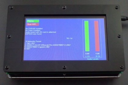
We have just introduced our new Project System for Teensy 4.1.
The Project System is designed to help in the creation of a finished touch LCD based project using the Teensy 4.1 microcontroller.
If you are like me, transitioning from a breadboard setup to something that is reasonably robust and looks presentable often presents challenges. The goal of this platform is to provide the user with a good starting platform that incorporates many of the key features that are often needed. That allows them to focus more on tailoring it for its final configuration. Optional acrylic panels provide an easy way to finish it off if doing a custom enclosure isn’t your thing.
The Project System is available in 3 flavors.
- Baseboard Only – PCB with all surface mount and thru-hole components mounted and standoffs to use for leg supports.
- Baseboard with LCD – As above, but also includes the LCD and a 4″ 40-conductor extender cable and standoffs to lay the LCD next to the baseboard for easy access during development work.
- Fully Stuffed version – As above and also includes an ESP32-S, Teensy Audio Adapter with 32GB SD card, 7.5VDC AC/DC adapter, power switch and 2 USB cables to connect to and work with both the Teensy and ESP32-S at the same time. If a Teensy 4.1 for Prototyping System is also ordered, it is installed and the example software is preloaded and the system will operate and demonstate some of its functionality out of the box.
Editorial note: Really need to change the name of the Teensy 4.1 for Prototyping System to something more generic like Teensy 4.1 for Baseboards.
For those familiar with our Prototyping System for Teensy 4.1, here is a quick look at how they compare.
Project System vs Prototyping System
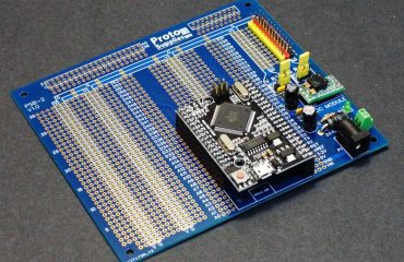
The Prototyping System for Teensy 4.1 has been popular with our customers as an easy way to work with Teensy 4.1 in a flexible bench setup that allows users to easily reconfigure and try different things. It provides a nice flexible Teensy 4.1 breadboarding setup of sorts.
The downside to the Prototying System is that it is not necessarily ideal for making a finished project that will be put into permanent use, though it does work OK for some applications.
The Project System is more tailored to making a 1-up finished project but still has many of the features of the Prototyping System and could even be used in place of it.
Both setups share a number of similarities but with some notable differences.
Both setups provide the following:
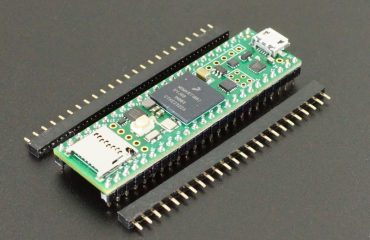
- Makes use of our customized DEV-26 version of Teensy 4.1 for Prototyping System which can include optional PSRAM and Flash memory and connect directly with I/O on the baseboard.
- Provide standard I/O built into the baseboard including Wired Ethernet, USB Host, CAN Bus and RS485 Bus.
- Provides an optional ESP32-S Coprocessor for WiFi and Bluetooth connectivity as well as additional processing and I/O capability.
- Provide an adapter area that can mount up to 2 smaller adapters like the Teensy Audio Adapter or can mount one large custom adapter up to 4” x 2.5” in size. Makes it easy for the user to design a small board to add functionality for their use case.
- For maximum flexibility all baseboard I/O connections other than the LCD, Ethernet and USB Host can be disconnected using jumpers so that the pins can be repurposed.
The Project System has the following major changes:
Board Size
Board size is increased to 8.7 x 5.3″ to accommodate the larger LCD and provide additional space for internally mounting 3rd party modules as well as supporting a potentally larger adapter board size of up to 4 x 5″.
LCD
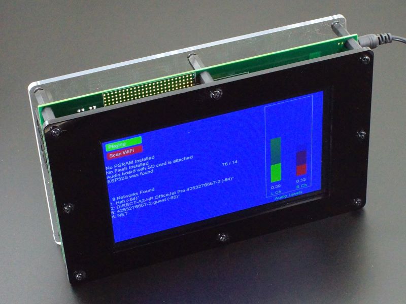
- It uses a much larger and higher resolution 7” 800 x 480 display with a multi-touch capable capacitive touchscreen.
- The LCD is the BuyDisplay ER-TFTM070-5 with 4-pin SPI/I2C and 5V operation. SKU: ER-TFTM070-5-3662-4SPI-5V-3403-3433.
- This display has good software support using the RA8875 Library which is part of Teensyduino.
- The LCD does not play nicely with other SPI devices, so it sits contently by itself on the SPI1 bus.
- The capacitive touchscreen requires no calibration and supports up to 5 simultaneous touches.
- The LCD mounts on the side of the PCB opposite the Teensy and other circuitry, which is good for a final packaging solution, but bad for working with the hardware.
- For development work, the LCD can be connected adjacent to the baseboard for easy access to everything using the supplied extender cable and standoffs. In this configuration it works similar to a larger version of our Prototyping System

Due to the power requirements of the LCD, while the baseboard can operate from USB power, the LCD requires external DC power to be connected in order to operate. When the LCD does not have power, a bus switch automatically disconnects the LCD from the Teensy 4.1 to prevent possible damage due to back-biasing.
Built-in MIDI Support
- It adds MIDI IN/OUT circuitry and connectors on the baseboard.
Built-in 2×20 I/O expansion connector
- Includes two high performance SN74CBTLV3251 1 x 8 analog mux chips with only 5 ohm impedance for reading potentiometers and switches.
- Includes an MCP23017 16-channel I2C I/O expander for digital input and/or output such as switches and LEDs.
- The I/O can be wired up as a 2×10 connector for either the analog mux or digital I/O or can be wired up as a 2×20 connector if using both. 3.3V power and ground pins are provided to support either configuration.
- This additional I/O can also be used internal to the Project System rather than coming out through a connector to an external device.
3rd Party Module Support
- Provides an area to mount arbitrary 3rd party modules.
- The bottom two rows are shorted together so that both male and female headers can be installed to allow the modules to be plugged into the female header and be temporarily wired up using breadboad jumpers while intially configuring and troubleshooting the system. The connections can then be made permanent if desired.
- 3.3v, 5V and GND rails provided in this area.
Input Power
- LIke the Prototyping System baseboard, USB power to the Teensy 4.1, ESP32-S and DC input can all be applied at the same time.
- The baseboard (minus the LCD) can be powered from USB. If only USB power is applied, the LCD is left unpowered and is logically isolated from the Teensy 4.1.
- Operation of the LCD requires external DC power to be applied as the current draw is too high to safely pull from USB.
- The DC Power Input uses a DC-DC converter front-end to allow for a wider input voltage range and lower power dissipation. The DC-DC converter is spec’d for up to 32V input, but recommend a 6-16VDC input to be on the safe side in case of voltage spikes when connecting power.
- A linear regulator is still used for the baseboard 3.3V power to ensure clean power on the 3.3V rail. The Teensy 3.3V output is not used on the baseboard to minimize the risk of damage to its regulator.
Project Housing
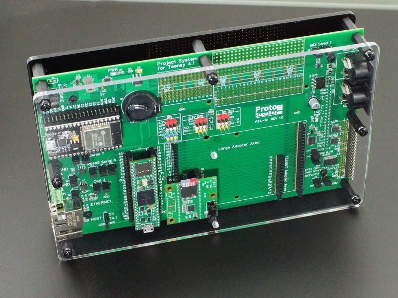
- An optional 2-panel acrylic enclosure is available to provide a basic packaging solution at a reasonable cost which will be suitable for many applications.
- The front is black and the rear is clear in fairly thick 4.5mm acrylic. M4 nylon hardware is provided for assembly.
- The assembly can lay flat on the bench or sit on edge. The sides are left open for easy I/O access. Longer standoffs are available if a thicker assembly is desired such as to mount taller modules.
Find more info on this system at https://protosupplies.com/product/project-system-for-teensy-4-1/

