PT8211 Audio Adapter for Teensy
$2.95 – $7.95
Low cost 16-bit stereo audio
Select Kit or Assembled
Description
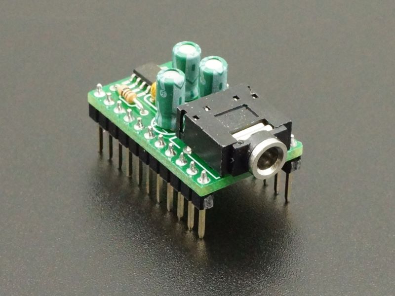
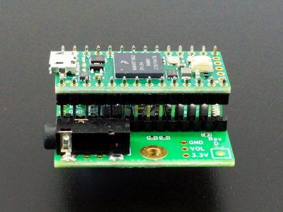
The PT8211 Audio Adapter is a low cost 16-bit stereo Digital to Analog (DAC) board with a line-level output for driving amplified speakers, stereo receiver, mixer or amplifier input. It is not meant to directly drive speakers or headphones, though it will generally drive headphones well enough to experiment with.
Its main claim to fame besides being inexpensive is that it is compatible with the awesome PJRC Audio System Design Tool: https://www.pjrc.com/teensy/gui/
The adapter is available in two versions:
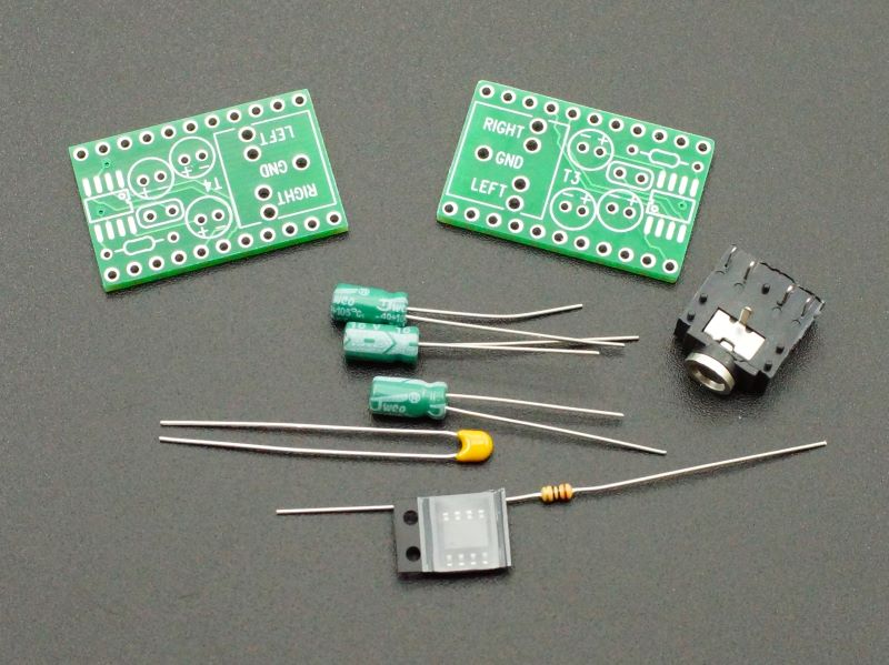
Kit: One is in a kit form with 2 PCBs. One PCB is for use with the Teensy 3.x boards and one is for use with the Teensy 4.x boards. The kit requires some surface mount and thru-hole soldering.
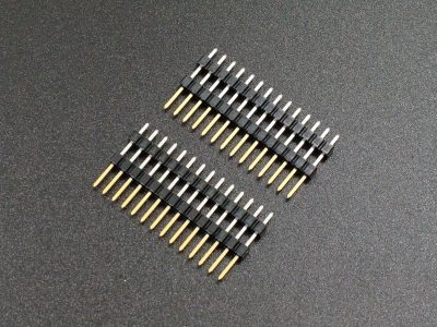
Fully Assembled: The other is a fully assembled version using the Teensy 4.x PCB and has male header pins installed as well. It is mainly for use with our Prototyping System for Teensy 4.1 baseboard but will also work in solderless breadboards and so will work with Teensy 3.x in breadboard setups where the pins don’t need to map one-to-one.
Package Includes:
- PT8211 Audio Adapter for Teensy (Kit or Fully Assembled)
KEY FEATURES OF PT8211 AUDIO ADAPTER FOR TEENSY:
- 16-bit stereo line-level output
- Fast switching R-2R resistor ladder network
- High speed serial bus
- AC coupled output
- 3.5mm audio jack
- 3.3V or 5V operation
Assembling the kit version
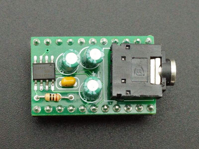
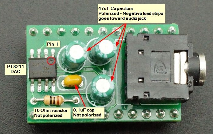
Assembling the board is fairly straightforward. Soldering the PT8211 SMD IC is the hardest part. Refer to the instructions and pic below for general guidance.
- Pick the PCB to match your Teensy (T3 for Teensy 3.x or T4 for Teensy 4.x.
- Install the PT8211 SMD IC. Observe the proper orientation of pin 1 and solder one pin in place. Ensure the IC is aligned to the pads properly and then solder the remaining pins.
- Install the 10 ohm resistor and small 0.1uF capacitor. Orientation does not matter. Trim the leads and solder in place.
- Install the phono jack. Solder one pin and verify jack is level and flush with the board and then solder the remaining pins.
- Install the three 47uF electrolytic capacitors. They have polarity and the negative (-) stripe must face towards the phono jack. Trim and solder the leads in place.
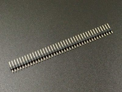
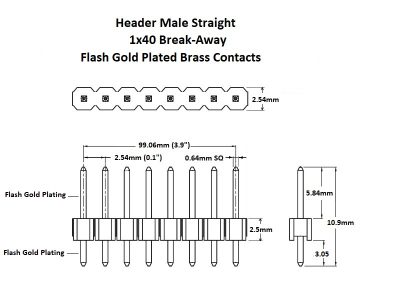
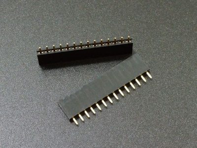
- Installation of male or female headers will depend on how you are going to be using the module. These headers are not part of the kit.
Further instructions for assembling the kit version and use with the Audio Design Tool can be found on the PJRC website: https://www.pjrc.com/store/pt8211_kit.html
Using the PT8211 Audio Adapter for Teensy
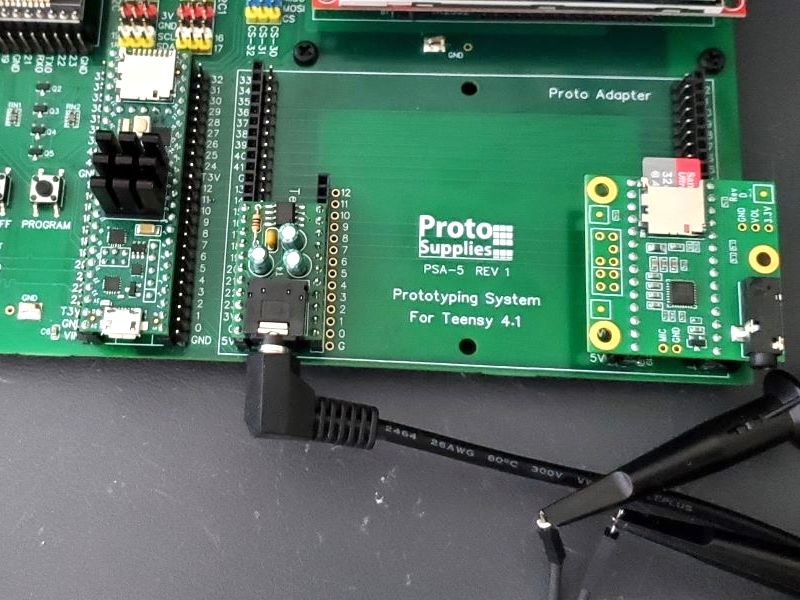
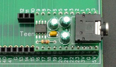
If you are using the module with the Prototyping System for Teensy 4.1 baseboard, a simple test to verify operation is to plug it into one of the two Teensy Adapter slots and run the Examples for Teensy 4.1 / Audio / HardwareTesting / PT8211Sine sketch. Since it is short, it is also shown here if you prefer to just copy and paste into the IDE.
#include <Audio.h>
#include <Wire.h>
#include <SPI.h>
#include <SD.h>
#include <SerialFlash.h>

// GUItool: begin automatically generated code
AudioSynthWaveform       waveform1;      //xy=110,75
AudioOutputPT8211        pt8211_1;          //xy=303,78
AudioConnection          patchCord1(waveform1, 0, pt8211_1, 0);
AudioConnection          patchCord2(waveform1, 0, pt8211_1, 1);
// GUItool: end automatically generated code

void setup() {
  AudioMemory(15);
  waveform1.begin(WAVEFORM_SINE);
  waveform1.frequency(440);
  waveform1.amplitude(0.99);
}

void loop() {
}
Note that the board is shorter than most Teensy Adapters and should be justified to the front of the slot as shown in the pic.
The board occupies pins 7, 20/A6 and 21/A7 which do not conflict with any pins on the Prototyping System or Project System for Teensy 4.1 baseboards.
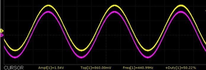
The program simply outputs a 440Hz sign wave on both channels which can be verified with either an O’scope or by plugging in headphones. The pic below shows the output of both channels captured on a O’scope.
Our Evaluation Results:
These boards work well for creating basic audio waveforms using the Teensy and have good library support.
It is highly recommended to checkout the PJRC website and forum at the links below for additional information. Some of the audio projects utilize these adapters.
Before they are shipped, these modules are:
- Optionally assembled and tested if ordered that way.
- Packaged in high quality resealable ESD bag for safe storage.
Further Reading:
PJRC Audio Forum – Excellent source of technical information
PJRC website – PT8211 Product Page – Good source of additional info on assembling and using the adapter
Notes:
- None
Technical Specifications
| I/O Logic Levels | 3.3V or 5V |
| Operating Voltage | 3.3 or 5V to match MCU |
| Board Dimensions (PCB) | 28 x 18mm (1.1 x 0.7″) |
| Mfr | PJRC |
| Datasheet | PT8211 |

