Thru-Hole and SMD – Adapter 1
$4.95
General purpose adapter for the Prototyping and Project System for Teensy 4.1 baseboards.
63 in stock
Description
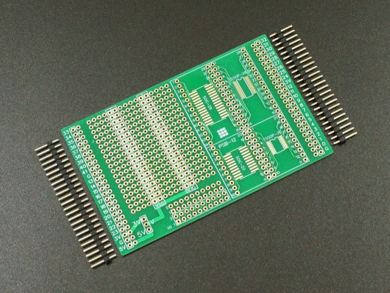
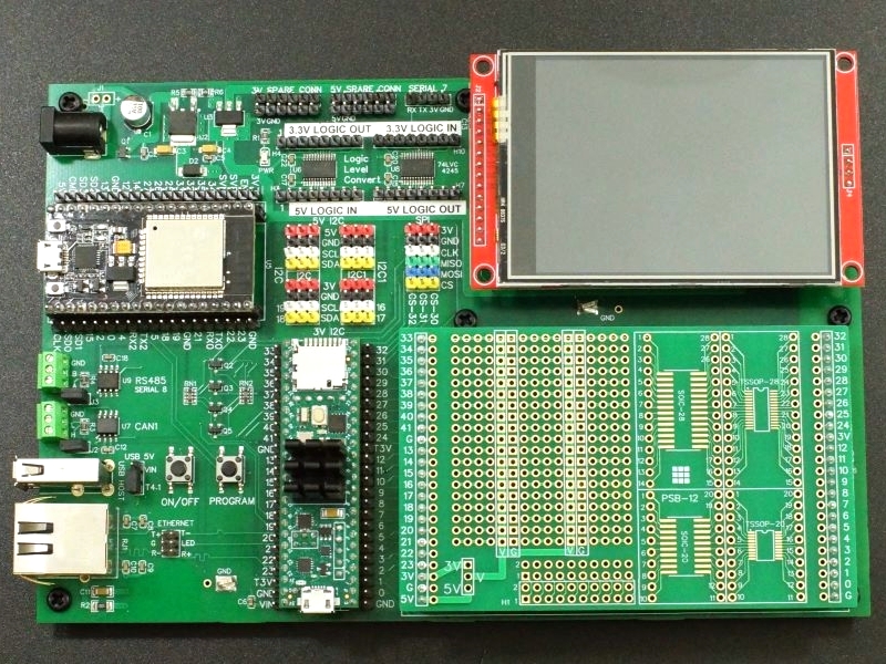
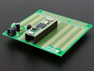
This general purpose prototyping adapter board plugs into the Prototyping and Project System for Teensy 4.1 baseboards extended adapter area for building permanent custom circuits.
PACKAGE INCLUDES:
- Thru-Hole and SMD – Adapter 1 PCB
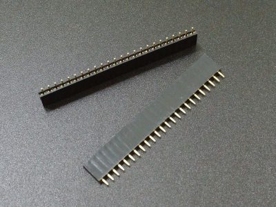
- Qty 2 – 1×24 male headers
KEY FEATURES OF PROTOTYPING SYSTEM FOR TEENSY 4.1 – ADAPTER 1:
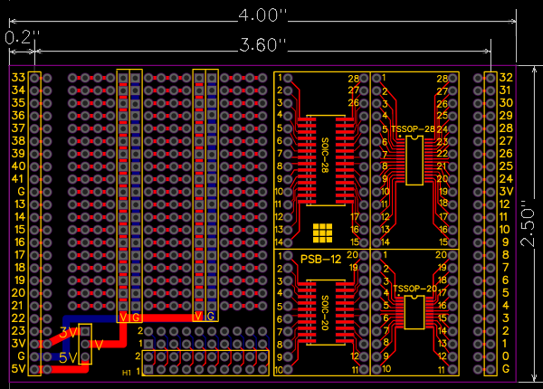
- Standard 0.1″ / 2.54mm hole patterns with 19 rows
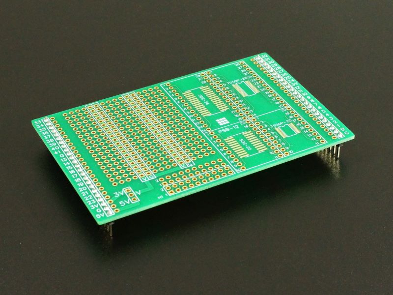
- Distributed power and ground with clear silkscreen top and bottom
- 3.3V or 5V selection for power
- 20-pin and 28-pin SOIC footprints
- 20-pin and 28-pin TSSOP footprints
- 2×10 connector area at front of board
- Edge connectors labeled with Teensy 4.1 pin numbers
- High quality construction with ENIG (Electroless Nickel Immersion Gold) finish
- Compact 4″ x 2.5″ size
Power Distribution
The V rail can be tied to either the 3V or 5V baseboard power rail with a jumper.
All power and ground runs are silk-screened on both sides of the board and the V and ground power rail pads are square to further clearly differentiate them.
If external power is brought directly into this board, it should not be connected to the 5V or 3V pins going to the baseboard.
Board Details
The headers along the edge of the board are labeled with the Teensy 4.1 pinout and have a solder pad adjacent to each pin for making connections.
All holes are large 40 mil plated through with large 70 mil pads. These are large enough to use with TO-220 type packages like power MOSFETs.
The 4-hole patterns have 30 mil traces connecting them on both the top and bottom of the board for good current handling capability.
The boards are constructed of 1.6mm FR-4 with 1oz copper.
The copper has an ENIG (Electroless Nickel Immersion Gold) finish for maximum performance. ENIG ensures extended shelf life against corrosion, provides excellent solderability with lead or lead-free solder, provides a completely flat soldering surface and gives good visibility of the soldered joints compared to the gold finish. It is also fully ROHS compliant.
Green solder mask provides the highest performance and also provides excellent trace visibility in case trace customization is desired.
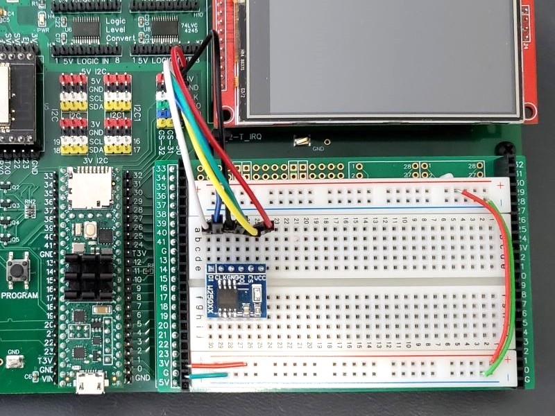
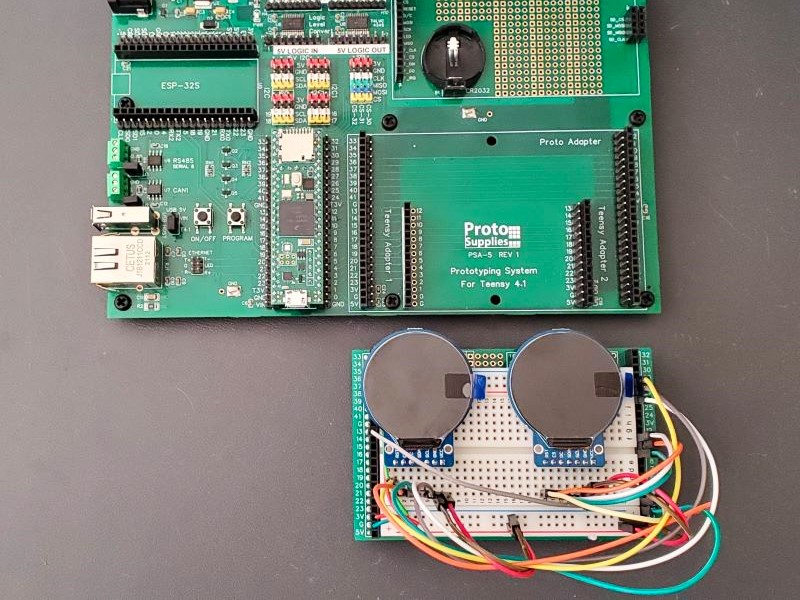
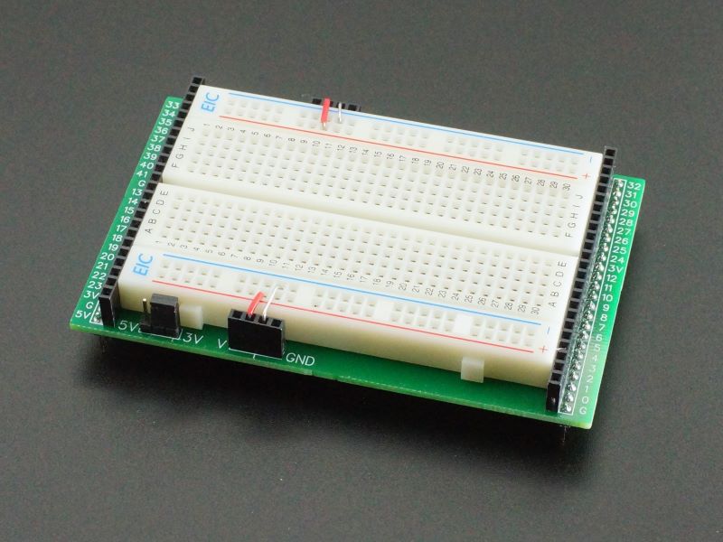
Use as a Solderless Breadboard Mount
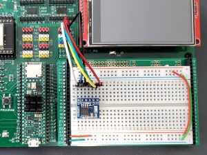
To do this, two 1×24 female headers are soldered to the extra holes on the two sides of the board for connecting to all of the Teensy signals. These can also be male headers if preferred.
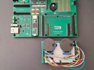
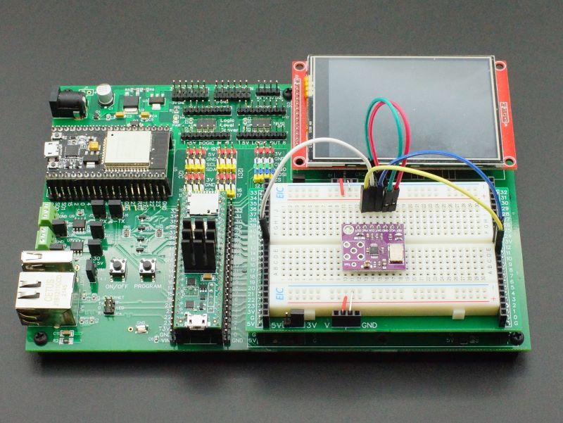
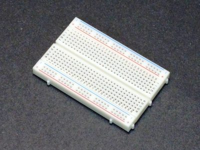
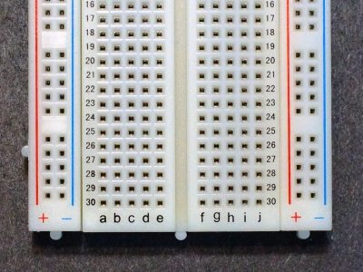
400 tie-point breadboards vary in size a bit. Our hobby line fits between the headers with a little room to spare. Our Pro Series breadboard shown in the picture requires that the small nubs at the end of the breadboard be cut off to have enough clearance to fit between the female headers and then it is still a snug fit.
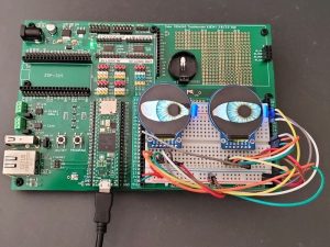
It positions the solderless breadboard close enough to the baseboard jumper points to use short breadboard jumpers to make the connections as we are doing in this picture to patch into the SPI bus headers.
Using jumpers between the breadboard and the 24-pin headers allows the breadboard setup to be kept intact when removed from the baseboard.
Parts used in this setup are shown at the bottom of the page.
Board Mounting
The board plugs into the outer 24-pin female headers on the Prototyping System for Teensy 4.1 and Project System for Teensy 4.1 baseboards.
Notes:
- None
Technical Specifications
| Material | FR-4 | |
| Copper | 1 oz, double-sided | |
| Plating | ENIG (Electroless Nickel Immersion Gold) | |
| Solder Resist | Green | |
| Silkscreen | Front and Back | White |
| Prototype Area | Holes, plated-thru | 1.02mm (0.04″) |
| Pads | 1.78mm (0.07″) | |
| Dimensions | Board outline | 101.6 x 63.5mm (4.0 x 2.5″) |
| Board thickness | 1.6mm (0.062″) | |
| Header row spacing | 91.44mm (3.6″) | |
| Country of Origin | Designed in USA | Manufactured in China |

