WS2812 Addressable LED Adapter
$17.95
For Prototyping System for Teensy 4.1
15 in stock
Description
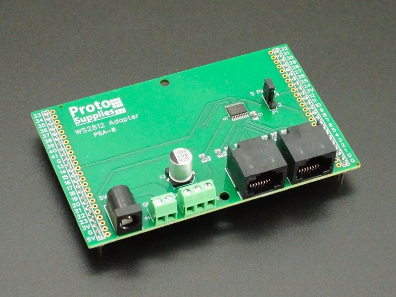
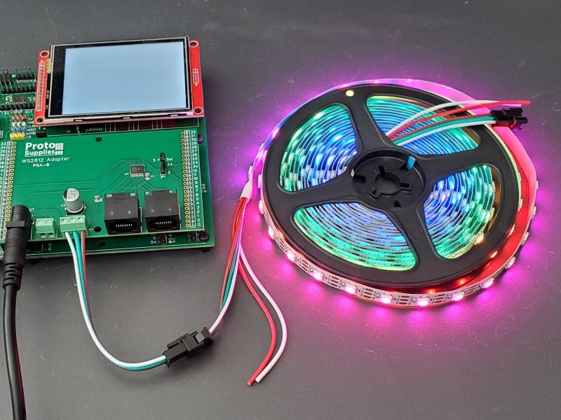
The WS2812 Adapter makes it easy to work with addressable LED strips while using the Prototyping System for Teensy 4.1.
This adapter can also be used with the Project System for Teensy 4.1 baseboard with the following caveats.
- Single channel output must be set for pin 24, and the MUX2 baseboard jumper J14(24) is removed (MUX2 disabled).
- On the 8-channel RJ45 outputs, pin 5 conflicts with the LCD and cannot be used, so is limited to 7-channels.
- If MUX1 is being used, it uses pin 6 for addressing, so the RJ45 outputs would be limited to 6-channels.
Package Includes:
- WS2812 Adapter fully assembled
KEY FEATURES OF WS2812 ADAPTER:
- Easily attaches directly to a single string of addressable LEDs
- Supports external 5V input to power a single string of addressable LEDs
- Supports same configuration as the OctoWS2811 module to drive larger arrays
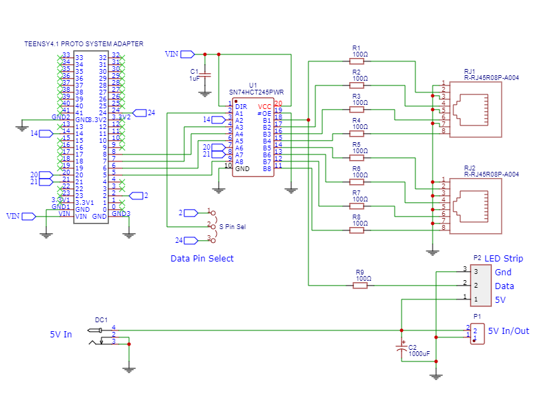
- Provides 5V logic level shifting
- 100 ohm series resistors on all data lines to minimize signal reflections
- 1000uF electrolytic capacitor for LED power surge protection
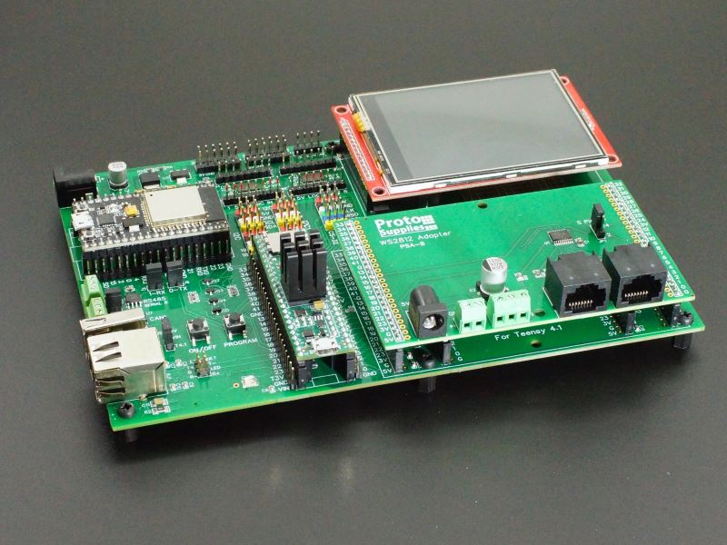
- Plugs into the Prototyping System for Teensy 4.1 proto adapter area
- Supports maximum of 1365 RGB or 1023 RGBW per output (Teensy 4.1 limit)
The WS2812 Adapter provides convenient 5V power connections and logic level shifted and buffered data connections for one string of up to 1365 RGB addressable LEDs to quickly and easily get up and running to start working with these fun peripherals.
The adapter also provides two RJ45 connectors with 8 logic level shifted and buffered data connections to provide the same functionality as the original PJRC OctoWS2811 adapter for driving larger LED arrays using CAT6 cable and external power. Though we sell the original OctoWS2811 adapter as well, it does not work well on the Prototyping System baseboard due to the connector orientation. The RJ45 connections also requires fairly extensive wiring to get started working with addressable LED strips and best suited for more series projects.
Using the WS2812 Adapter with the Single LED Strip Connections
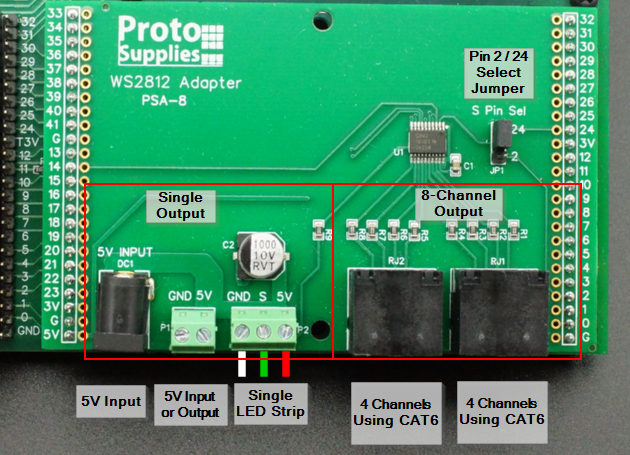
The WS2812 Adapter occupies the entire proto adapter area and inserts into the outer 24-pin female headers.
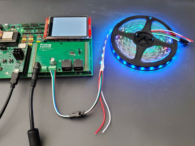
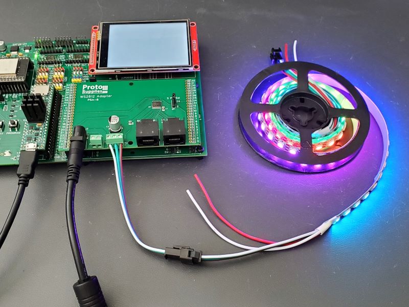
The connections on the left side of the adapter marked ‘Single Output’ allow for simple connection to a single strip of LEDs for easily working with it. More than one strip can be connected in series, but they will share the same data pin.
Connecting 5V Input Power
The adapter has a standard DC power jack (DC1) for connecting an external 5V power supply to power the single LED strip output. Alternatively, a 2-pos screw terminal next to it (P1) can be used to connect to a 5V power source. The baseboard 5V power is not used to power the LEDs to avoid possible power issues with the other circuits. A large 1000uF capacitor is included to help safeguard the LEDs from power surges. The baseboard 5V is used to power the 74HCT245 level shifter on the adapter.
If the standard DC power jack is used to input 5V power, the 2-pos screw terminal can alternately be used as an auxiliary output power connection for the extra power leads of the LED strip. This might be handy if pushing the current limits and the screw terminals can be used to connect power to the power leads at the far end of the cable to minimize voltage drop across the strip.
Take note that the LED strips can be quite power hungry depending on the number of LEDs and how they are driven. At full brightness and when driving white (red/green/blue LEDs all full on), each LED can draw up to 60mA / 0.3W of power. A 5 meter strip with 300 LEDs can therefore draw up to 18A / 90W of power. Since the LEDs can be annoyingly bright at full power, when working with them on the bench they can be set down around 10% brightness and then they only draw about 1.8A max and you can get away with a 2A power source. In our example program below that creates bouncing colored balls, you can easily run two 15 foot strips (30 ft / 600 LEDs total) from just a standard 1A wall wart since only a few LEDs are being lit at any one time.
When connecting or disconnecting the LED strip, the external 5V power should be removed first to minimize the risk of damage to the LEDs.
Connecting Data
The adapter has a 74HCT245 IC which is used to logic level shift the 3.3V logic from the Teensy 4.1 up to 5V to properly drive the LEDs. It also provides some buffering and protection for the Teensy pins. The output has a 100 ohm series resistor to minimize signal reflections.
A jumper (S Pin Sel) allows either pin 2 or pin 24 of the Teensy to drive the data to the LED strip. Pin 2 is also connected to the LCD interrupt output if the LCD is installed so pin 24 is usually the easiest pin to use since there are no other conflicts on the baseboard.
Note: that as of Rev 1.1 of the Prototyping System for Teensy 4.1 baseboard, there is a jumper to remove the LCD interrupt on pin 2.
Connecting the LED Strip
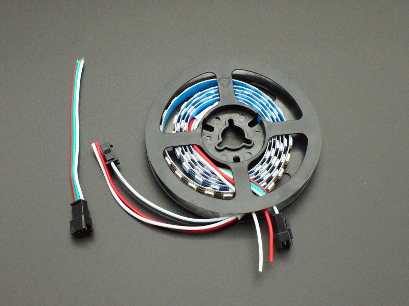
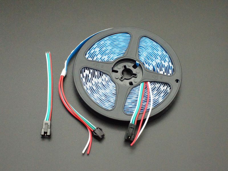
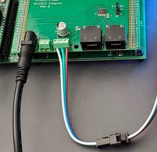
A 3-pos screw terminal allows for easy hookup of the typical male JST-SM connector pigtail supplied with standard LED strips like the ones we provide. The female (input) end of the LED strip then plugs into the male connector on this pigtail.
3-POS Screw Terminal (P2):
- GND – White wire is ground
- S – Green Wire is the Signal / Data
- 5V – Red wire is 5V
Using the WS2812 Adapter with Multiple LED Strips Using the RJ45 Connectors
The RJ45 connectors on the right side of the adapter allow for connecting to multiple LED strips using CAT6 cabling for larger and more complex LED projects. The OctoWS2811 library supports using these connections.
Connecting 5V Power
In this case, 5V power to the LEDs would be delivered from one or more power supplies directly to the LED strips. The power would not come through the adapter.
Connecting Data
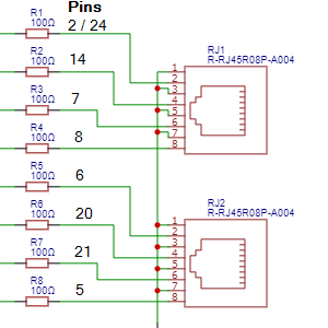
The original OctoWS2811 PJRC adapter uses pins 2, 5, 6, 7, 8, 14, 20 and 21 which are also used on this adapter tp keep compatibility. Pin 2 is shared with the single strip connection and as in that case, the S Pin Sel jumper allows either pin 2 or pin 24 of the Teensy to be used. Since pin 2 is also connected to the LCD interrupt output if the LCD is installed, pin 24 is usually the easiest pin to use since there are no other conflicts with the other pins on the baseboard. The pins can be remapped in the OctoWS8211 library. The File/Examples/OctoWS2811/Teensy4_PinList example in the IDE shows how to define the pins to use.
Note: that as of Rev 1.1 of the Prototyping System for Teensy 4.1 baseboard, there is a jumper to remove the LCD interrupt on pin 2.
Connecting the LED Strips
Connecting to the LED strips to the RJ45 outputs requires cutting CAT6 cable, stripping the individual wires and connecting to the LED strips which are usually mounted remotely to some structure. This allows the LEDs to be positioned some distance from the Teensy 4.1.
The process for doing this is the same as the OctoWS2811 adapter so I will refer you to the PJRC OctoWS2811 Adapter product page for more details on wiring up the LEDs in this configuration.
Running an Example Program
Recommend leaving PIN set to 24 to match the jumper on the adapter, but adjust the NUM_LEDS constant if you are using a different size of LED strip.
The program itself is adapted from a program on the Tweaking4All.com website which also has other interesting examples using addressable LEDs as well and are written to use either the NeoPixel or FastLED libraries. We have modified this one to use NeoPixel.h library only just to make it simpler.
This program creates 7 colored ‘balls’ that launch from the start of the LED strip at different impact velocities similar to how a pinball machine launches pinballs and they bounce back and forth on the LED strip with their velocities slowly decaying. It is easy to change the number and colors of the balls by modifying the colors array shown below.
// This array defines the number and color of the balls.  If you change the
// number of balls from 7, also change the number in the function call in the
// main loop BouncingColoredBalls(7, colors);
  byte colors[7][3] = { {0xff, 0,0},       // red
                        {0, 0xff, 0},      // green
                        {0, 0, 0xff},      // blue
                        {0xff, 0xff, 0xff},// white
                        {0xff, 0xff, 0},   // yellow
                        {0, 0xff, 0xff},   // Cyan
                        {0xff, 0, 0xff}   // Purple
                        };
The brightness is set to 25 out of 255 (about 10% brightness) using strip.setBrightness(25); but you can set this to any brightness you want since only a few LEDs are being lit at a time.
It uses the NeoPixel library by Adafruit which can be downloaded from the IDE Library Manager.
Bouncing Balls Example Program
/*
 * Bouncing Balls WS2812 Adapter Demo
 *
 * This program is adapted from a demo on Tweaking4All.com
 * Bounces 7 balls (red/green/blue/white/yellow/cyan/purple) similar to how
 * a pinball machine launches balls, using different velocities
 *
 * Uses adafruit_NeoPixel library
 * Adjust the pin number (24/2) depending on the board jumper setting
 * Set the number of LEDs in the strand you are using.  We are using a
 * standard 5m / 15ft stand of 300 LEDs
 */
#include <Adafruit_NeoPixel.h>
#define PIN 24
#define NUM_LEDS 300
// Parameter 1 = number of pixels in strip
// Parameter 2 = pin number (most are valid)
// Parameter 3 = pixel type flags, add together as needed:
//   NEO_KHZ800  800 KHz bitstream (most NeoPixel products w/WS2812 LEDs)
//   NEO_KHZ400  400 KHz (classic 'v1' (not v2) FLORA pixels, WS2811 drivers)
//   NEO_GRB     Pixels are wired for GRB bitstream (most NeoPixel products)
//   NEO_RGB     Pixels are wired for RGB bitstream (v1 FLORA pixels, not v2)
Adafruit_NeoPixel strip = Adafruit_NeoPixel(NUM_LEDS, PIN, NEO_GRB + NEO_KHZ800);

// This array defines the number and color of the balls.  If you change the
// number of balls from 7, also change the number in the function call in the
// main loop BouncingColoredBalls(7, colors);
  byte colors[7][3] = { {0xff, 0,0},       // red
                        {0, 0xff, 0},      // green
                        {0, 0, 0xff},      // blue
                        {0xff, 0xff, 0xff},// white
                        {0xff, 0xff, 0},   // yellow
                        {0, 0xff, 0xff},   // Cyan
                        {0xff, 0, 0xff}    // Purple
                        };

//===============================================================================
//  Initialization
//===============================================================================
void setup() {
  strip.begin();
  strip.show(); // Initialize all pixels to 'off' immediately
  strip.setBrightness(25); // Set brightness 1-255
}
//===============================================================================
//  Main
//===============================================================================
void loop() {

  BouncingColoredBalls(7, colors);
}
//===============================================================================
//  BouncingColoredBalls routine is where all the magic happens
//===============================================================================
void BouncingColoredBalls(int BallCount, byte colors[][3]) {
  float Gravity = -9.81;
  int StartHeight = 1;

  float Height[BallCount];
  float ImpactVelocityStart = sqrt( -2 * Gravity * StartHeight );
  float ImpactVelocity[BallCount];
  float TimeSinceLastBounce[BallCount];
  int   Position[BallCount];
  long  ClockTimeSinceLastBounce[BallCount];
  float Dampening[BallCount];

  for (int i = 0 ; i < BallCount ; i++) {
    ClockTimeSinceLastBounce[i] = millis();
    Height[i] = StartHeight;
    Position[i] = 0;
    ImpactVelocity[i] = ImpactVelocityStart;
    TimeSinceLastBounce[i] = 0;
    Dampening[i] = 0.90 - float(i)/pow(BallCount,2);
  }

  while (true) {
    for (int i = 0 ; i < BallCount ; i++) {
      TimeSinceLastBounce[i] =  millis() - ClockTimeSinceLastBounce[i];

      Height[i] = 0.5 * Gravity * pow( TimeSinceLastBounce[i]/1000 , 2.0 )
        + ImpactVelocity[i] * TimeSinceLastBounce[i]/1000;

      if ( Height[i] < 0 ) {
        Height[i] = 0;
        ImpactVelocity[i] = Dampening[i] * ImpactVelocity[i];
        ClockTimeSinceLastBounce[i] = millis();

        if ( ImpactVelocity[i] < 0.01 ) {
          ImpactVelocity[i] = ImpactVelocityStart;
        }
      }
      Position[i] = round( Height[i] * (NUM_LEDS - 1) / StartHeight);
    }

    for (int i = 0 ; i < BallCount ; i++) {
      strip.setPixelColor(Position[i], strip.Color(colors[i][0], colors[i][1], colors[i][2]));
    }

    strip.show();
    setAll(0,0,0);  // Set all pixels Off
  }
}
//===============================================================================
//  setAll Routine sets all pixels to same color or off
//===============================================================================
void setAll(byte red, byte green, byte blue) {
  for(int i = 0; i < NUM_LEDS; i++ ) {
    strip.setPixelColor(i, strip.Color(red, green, blue));
  }
  strip.show();
}
Further Reading:
Notes:
- None
Technical Specifications
| Max LEDs per output | RGB | 1365 |
| RGBW | 1023 | |
| PCB Material | FR-4 | |
| Copper | 1 oz, double-sided | |
| Plating | ENIG (Electroless Nickel Immersion Gold) | |
| Solder Resist | Green | |
| Silkscreen | Front and Back | White |
| Board Dimensions (PCB) | W x H | 101.6 x 63.5mm (4.0 x 2.5″) |
| Country of Origin | Designed in USA | Manufactured in China |
You may also like…
-
Select options This product has multiple variants. The options may be chosen on the product page
Prototyping System For Teensy 4.1
$69.95 – $149.95Platform for working with the powerful Teensy 4.1

