Feather Adapter
$9.95 – $14.95
For Prototyping System for Teensy 4.1
Select Kit or Assembled
Description
Adafruit, the well-known electronic hobbyist company, created a product line made up of Feather boards which are small development boards based on various microcontrollers and stackable daughter boards called ‘Wings’ or ‘FeatherWings’.
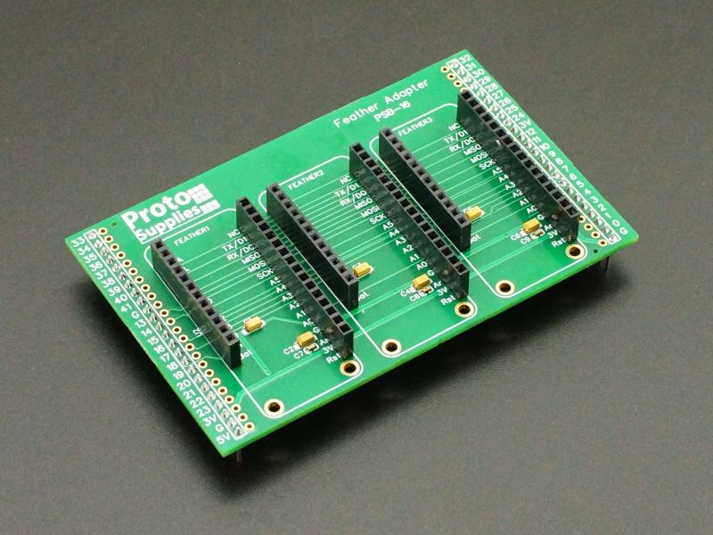
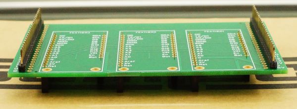
The Feather Adapter treats the Prototyping System for Teensy 4.1 like another Feather development board and in turn mounts up to 3 of the FeatherWings for easily working with them.
If considering it for use with the Project System for Teensy 4.1, check the pin usage of the intended FeatherWings agains the pin usage of the Project System for Teensy 4.1 baseboard to ensure there are no conflicts that can’t be overcome by removing jumpers.
The Feather Adapter is available in two versions:
Kit: One is in a kit form. All components are thru-hole and fairly easy to solder with basic soldering skills.
Fully Assembled: The other is a fully assembled version that is ready to plug into the Prototyping System for Teensy 4.1 baseboard.
Package Includes:
- Feather Adapter (Kit or Fully Assembled depending on selection)
KEY FEATURES OF FEATHER ADAPTER:
- Mounts up to 3 Adafruit FeatherWings
- Includes 10uF tantalum and ceramic decoupling SMD capacitors preinstalled on the power pins.
- Plugs into the Prototyping System for Teensy 4.1 proto adapter area
Assembling the kit version
Assembling the board is straightforward since all components that need to be installed are thru-hole. The SMD capacitors come soldered onto the board. Keeping the headers straight relative to the PCB is the trickiest part of assembly.
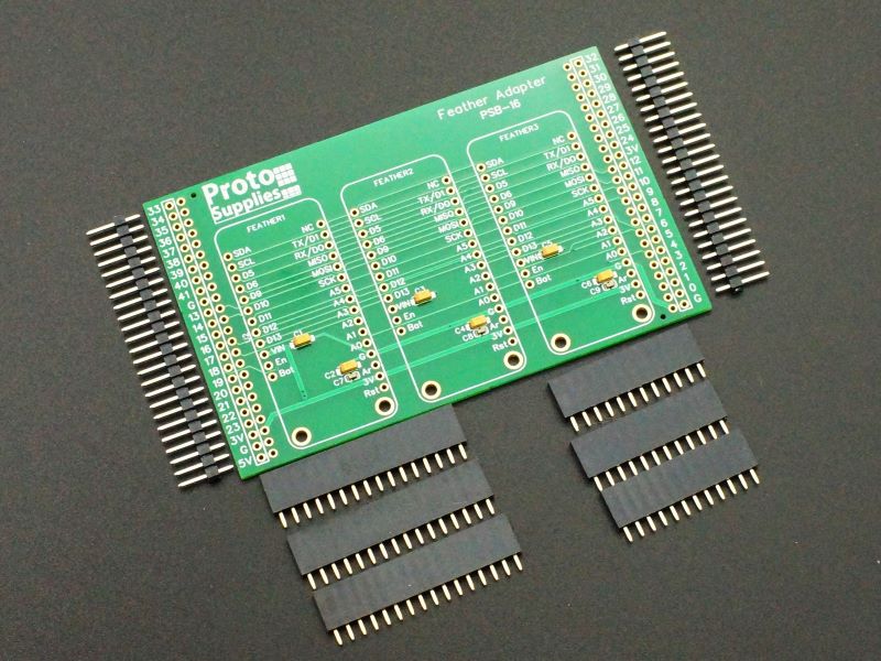
The female headers go on the top-side of the adapter with the logo showing. The male headers go on the bottom side.
To solder the male headers, they can be inserted into a couple of solderless breadboards to hold them in position for soldering or they can be placed into the female headers on the Prototyping System for Teensy 4.1 baseboard to keep them aligned while soldering. The headers go into the outside rows of holes that is outlined by the silkscreen and near the pin numbers. The inside holes are there in case you want to run some additional point-to-point wiring or to probe signals.
For soldering the female headers, they can all be placed into the board since the male headers will keep the board raised up for pin clearance on the bottom. Then lay something flat and stiff, like the side of a small cardboard box, over the female headers to keep them in place while carefully inverting the board for soldering. The female headers will usually stay fairly straight and stable while soldering since there are six of them for the board to rest on, but it is a good idea to solder just the end pins and then check to ensure the female headers are straight. If necessary, they can be easily straightened before soldering the remaining pins since the female headers use flat-sided pins that easily bend unlike male headers with square pins.
Using the Feather Adapter
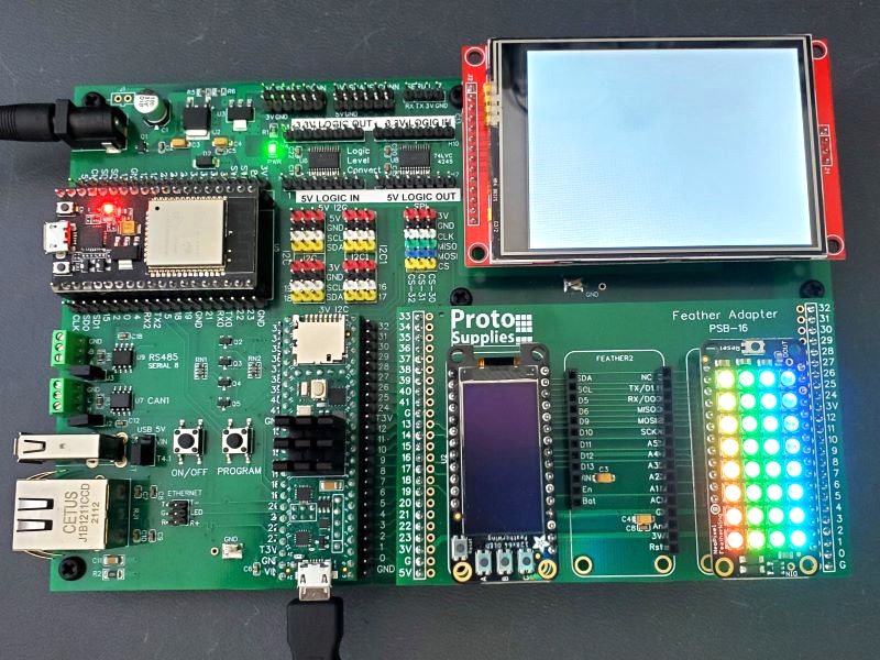
The Feather Adapter occupies the entire proto adapter area and inserts into the outer 24-pin female headers. Up to 3 FeatherWings can be installed. In the example below there is an OLED display and a NeoPixel array.
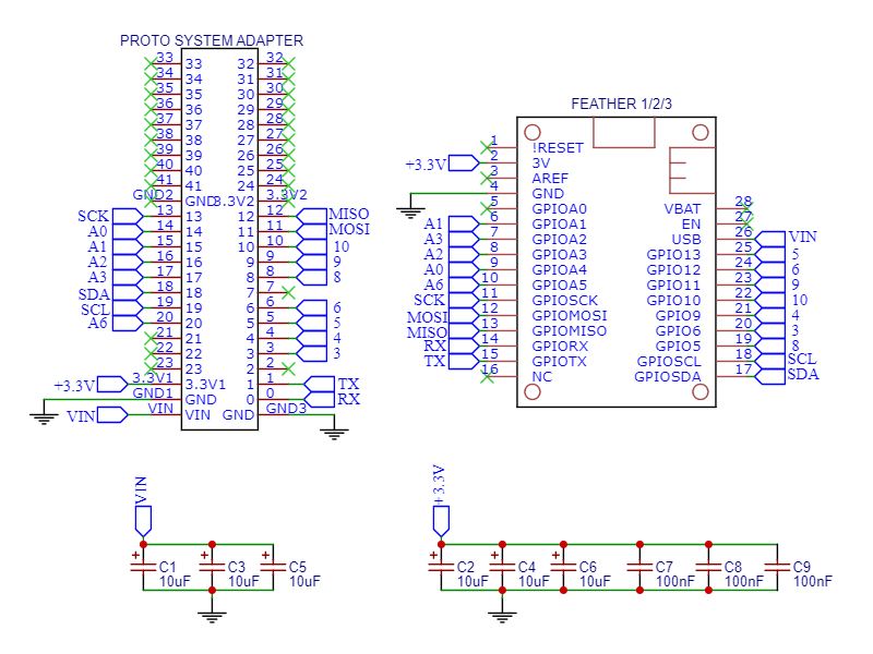
The pinout for this adapter uses the same pinout as the original Adafruit Teensy 3.x Feather Adapter. That adapter allowed FeatherWings to be mounted as a daughterboard on top of the Teensy 3.x boards.
Power, ground and the I2C and SPI buses are all connected where you expect them to be. It uses the main I2C bus on pins 18 & 19 and the main SPI bus on pins 11, 12 & 13.
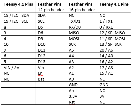
When it comes to individual digital pins and example programs, in some cases you may need to remap them. For instance, the NeoPixel FeatherWing shown here by default is looking for data on D6 which maps to pin 3 on the Teensy as shown in the pinout chart below. The FeatherWing allows you to cut a trace and solder bridge pads to change the pin used, but it is easier to just remap the pin in the code.
Feather Adapter Pinout
In some example programs, #define statements are used to remap the pins automatically depending on the target device. Teensyduino is the software that allows Teensy to work with the Arduino IDE. In the example code below, whenever the target is a Teensy, button A is being mapped to Teensy pin 4, button B to pin 3 and button C to pin 8.
#elif defined(TEENSYDUINO)
  #define BUTTON_A  4
  #define BUTTON_B  3
  #define BUTTON_C  8
The following Feather pins are not connected (NC) to the Prototyping System for Teensy 4.1 baseboard by the adapter.
- Bat – Power that would normally come from an external LiPoly battery.
- En – Enable input used to enable/disable the Feather power which is non-applicable with this baseboard. Though it could be wired to ON/OFF on the Teensy, that pin is not available on the proto adapter area headers.
- Rst – Reset, also non-applicable since Teensy 4.1 does not have a reset pin.
- Aref – Analog reference. Teensy 4.1 does not have an Aref voltage output. If needed, the Aref pin can be connected to the adjacent 3V pin on one of the female headers to provide a 3.3V reference voltage.
- A0 – This is an analog input to the FeatherWing such as may be used for simple mono audio applications. Teensy 4.1 does not have an analog output so this is left unconnected.
- NC – This is a free pin on the FeatherWings and is not normally connected to anything.
Further Reading:
You can checkout the available FeatherWings on the Adafruit website: https://www.adafruit.com/category/945
Notes:
- None
Technical Specifications
| PCB Material | FR-4 | |
| Copper | 1 oz, double-sided | |
| Plating | ENIG (Electroless Nickel Immersion Gold) | |
| Solder Resist | Green | |
| Silkscreen | Front and Back | White |
| Board Dimensions (PCB) | W x H | 101.6 x 63.5mm (4.0 x 2.5″) |
| Country of Origin | Designed and final assembly in USA | Manufactured in China |
You may also like…
-
Select options This product has multiple variants. The options may be chosen on the product page
Prototyping System For Teensy 4.1
$69.95 – $149.95Platform for working with the powerful Teensy 4.1

