Mega Breadboard
As you can probably imagine I spend considerable time evaluating and testing products. Much of that work requires using a typical solderless breadboard setup with an Uno or Mega 2560 and wiring things up as needed.
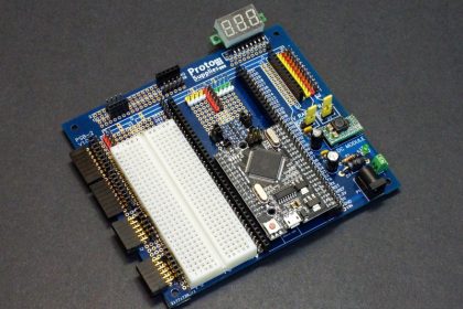
To create a better, more efficient test setup, I decided to utilize the new Mega 2560 Pro MCU Proto Board to create a dedicated breadboard setup with convenient mounting points for modules, displays and servos for testing and evaluating.
I discovered that the setup works quite well for a lot of general project breadboarding and others might find a similar setup useful, so I am documenting it here.
Project Definition:
- Use the Mega 2560 Pro MCU Proto Board as platform since it has plenty of I/O for any testing or project requirement.
- Provide access to all of the Mega 2560 Pro MCU module I/O pins with both male and female headers to allow easy connection to any I/O pins on the module.
- Allow modules such as joysticks and rotary encoders to be easily plugged in and used.
- Allow for easy access to calibration pots by providing both horizontal and vertical mounting.
- Provide DVM module for easily monitoring voltages or adjusting the built-in DC-DC converter module.
- Install a 4-channel logic level converter with jumper points for easily working with 3.3V modules.
- Bring I2C and SPI buses out to labeled connection points to easily connect multiple devices if needed.
- Add a couple LEDs with current limiting resistors and a pushbutton switch with pull-up resistor in case I need a logic indicator or to activate a test case.
- Include a small solderless breadboard area to give a flexible prototyping area.
Component list
With our project definition complete, we were able to create the list of part requirements.
| $13.95 | For the baseboard, the Mega 2560 Pro MCU Proto Board with component kit is used. | 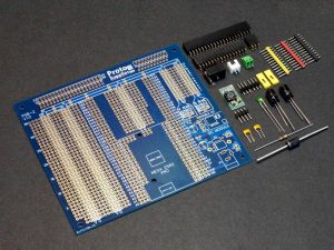 |
| $13.95 | For the microcontroller, the Mega 2560 Pro is the only option since it works with the Mega 2560 Pro MCU Proto Board | 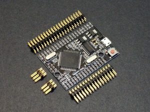 |
| $3.95 | For the built-in DVM, I picked the blue Mini DVM 0-100VDC 3-wire module. I like the blue, but they also available in red, yellow and green. | 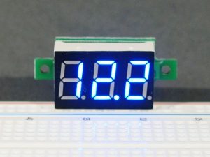 |
| $.79 | For logic level translation, I used the Logic Level Converter 4-Ch Bi-Directional Module. It works well, inexpensive and 4 channels is usually plenty. |  |
| $3.95 | For a solderless breadboard section, I used the Pro Series 400-tie point breadboard and removed the power/ground rails on both sides so it would fit. | 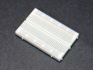 |
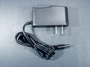
| $4.95 | For powering the setup, I used our AC Adapter 7.5V 1A wall bug.These are really nice as the lower voltage puts less strain on the downstream 5V regulators.
If working with higher than 6V on the board, you may want to go with a 12V adapter. |
 |
| Various prices |
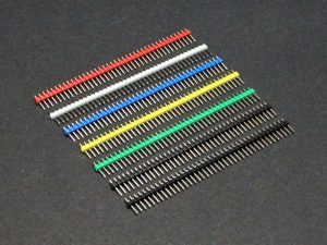
The headers used are fairly arbitrary depending on how you plan to use the platform, but I used the following:
Single-row male headers in black and multi-colored, snapped to the lengths required. Female headers in 2-pin, 5-pin, 6-pin and 8-pin 8-pin stackable headers which I bent to make right angle connectors and then cut the excess pin length off. Double-row right angle 6-pin female headers from my junk bin. These could also have been stackable 6 or 5-pin headers bent to right angle as well. Right angle male header for mounting the DVM Other incidentals include: LEDs |
 |
The Build
The actual build was straightforward.
The Mega 2560 Pro MCU Proto Board is assembled normally as is outlined on its product page as is the Mega 2560 Pro module that goes on it.
The main thing was deciding where to place the misc headers for connecting modules and associated jumper points. Dry placing all the module headers first before committing to soldering them in is important as unsoldering headers is not a fun project. If you do need to unsolder a header (as I did), you can unsolder each pin individually and pull them out one-by-one. Then if necessary go back and remove the solder from holes.
You want to ensure that the headers for connecting modules are positioned to run perpendicular to the connection points so each pin of the header is separate from each other. The male and/or female headers for making jumper connections are positioned parallel to the module headers so that the board traces make all the connections for you without having to connect any wires. I only have about 10 wires on the back of the board to connect everything up.
Basic Mega 2560 Pro MCU Proto Board
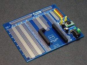
It includes a socket for the MCU module and a DC power input circuit on the right side that includes an MP2315 DC-DC converter which is very handy for powering servo motors and the like. Besides being able to adjust the voltage on that rail, it also provides some protection from the electrical noise create by the servo motors. More information can be found on the product page for the board.
Mega 2560 Pro MCU I/O Connections
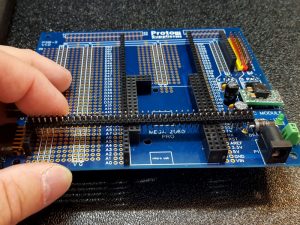
I simply soldered both a 40 pin female and male header into each side of the module to have two connections points for each pin. I cut the connectors down to 38 pins before soldering them in.
I found that using other opposite sex headers to hold the headers I was soldering in place helped in a number of areas like this one.
Module Connections
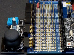
I used larger connectors for maximum flexibility with modules that have different number of pins, but you do need to ensure you offset the module and jumpers to match up as it is easy to get a pin off.
The front two connectors I used double row right-angle female headers for added strength as I planned to use these mainly for user input devices like a joystick. Single row headers should work OK as well.
For the other single row right-angle headers I used the stackable headers since they had long pins and I could bend the pins at a right angle before soldering and cutting the pins to length.
A couple of vertical female headers were placed along the back edge mainly for OLED display and ultrasonic sensor type of modules
Bus Connections
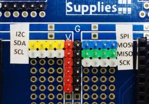
I then created some high quality labels since I won’t remember the color codes I assigned.
These pins are wired to the MCU I2C and SPI bus pins as follows:
I2C
- SDA – Yellow is connected to D20
- SCL – White is connected to D21
SPI
- MOSI – Blue is connected to D51
- MISO – Green is connected to D50
- SCK – White is connected to D52
I didn’t bother bringing the TX/RX serial lines out to breakout headers since these are clearly marked on the board and I never hook up more than one anyway.
If these buses are not being used, those pins can be used for general purpose I/O as well.
Logic Level Converter
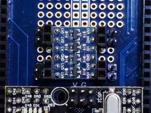
I used the bi-directional 4-channel module as it works well and is inexpensive and I never need more than 4 lines.
I permanently wired the LV pin to the 3.3V pin on the Mega 2560 Pro module and the HV pin the the V Rail which will typically be 5V. I did not hookup the ground pins as they are not used on the module.
I then soldered both male and female 2-pin headers on the LV1-4/HV1-4 lines for maximum flexibility. 5V signals from the MCU connect to the right side and 3.3V modules connect to the left side.
DVM
I love these little DVM modules. They can be quite handy for making basic voltage measurements without hauling out a meter and trying to hold the probes while also manipulating a pot or something.
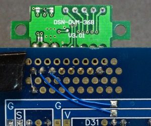
Some DVM modules will have flat solder pads where the wires were and others will have through holes were the wires are attached and may have 8 or 5 total pins that can be soldered to. I cocked the right-angle connector a little to give a bit of an angle to the DVM for easier viewing. I mounted it in the offset header area on the back right side of the board since I wasn’t using that area for anything else.
To wire it up, take note of which color of wire goes to each of the pads before removing them as they vary between different versions of this device. Wire the pad for the red wire to the V Rail and wire the pad for the black wire pad to a ground point. The white wire is the voltage to be measured. If you put a male pin the the connection point as I did, you don’t need to wire anything since a trace already connects the two, but I did anyway for apparently no reason at all.
The Finished Assembly
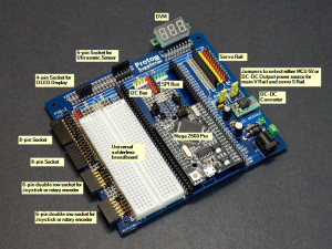
For the solderless breadboard I removed the power/ground rails from a 400 tie-point to allow it to fit in the space available. My intent was to stick it down but it covers the I/O labeling so I left it loose so it could be inserted only when it was needed which isn’t all that often.
Putting it to Use
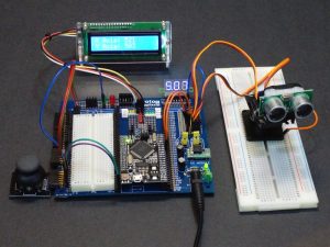
As a test application, I connected a joystick, 16×2 I2C LCD display and 2-axis servo platform. The joystick moves the servos and the LCD displays the joystick readings. Not an overly complex setup, but it utilizes some of the key features of the setup.
The LCD simply connects to the I2C headers including power and ground.
The joystick plugs into the first horizontal header and then is jumpered to the analog pins on the Mega 2560 Pro used to monitor potentiometer outputs. This connector also requires power and ground. A jumper connects from the button to the green LED to show when the button is depressed. It was at this time that I realized it was dumb to put the jumper connection in front of the LED since it partially blocks the view.
The DVM is jumpered to the S Rail which is jumpered to use the DC-DC converter output so I could adjust the voltage on the S Rail to 5V to power the servos. These tiny DC-DC converters work very well, but the tiny single turn pot prevents hitting an exact voltage setting. I just keep the setting within 5% and call it good.
The servo connectors simply plug into the S Rail. Ensure the orange signal wire is plugged into the yellow header. Two PWM outputs of the Mega 2560 Pro are used to control the servos.
Mega Breadboard Test Application
/*
  Mega Breadboard Example
  Uses 2-Axis Pan Tilt Mount with Servos, Joystick control
  and I2C 16x2 LCD

  This software utilizes a joystick control module to control 2 servos
  that are mounted on a pan / tilt bracket.

*/
#include "Servo.h"
#include <Wire.h>
#include <LiquidCrystal_I2C.h>

int const X_SERVO_PIN = 9;   // Can use any PWM pin
int const Y_SERVO_PIN = 10;  // Can use any PWM pin
int const X_PIN = A1;        // Use any analog pin to read joystick X-Axis pot
int const Y_PIN = A0;        // Use any analog pin to read joystick Y-Axis pot
int const X_MIN_VALUE = 10;   // Minimum X Servo position
int const X_MAX_VALUE = 180;  // Maximum X Servo position
int const Y_MIN_VALUE = 0;    // Minimum Y Servo position
int const Y_MAX_VALUE = 180;  // Maximum Y Servo position

int xPosition = 0;          // Variable to hold current X-Axis reading
int yPosition = 0;          // Variable to hold current Y-Axis reading
int buttonState = 0;        // Variable to hold current button state
int x_servo_pos = 0;       // Current X servo position
int x_servo_pos_old = 0;   // Used to hold old X servo position to look for change.
int y_servo_pos = 0;       // Current Y servo position
int y_servo_pos_old = 0;   // Used to hold old Y servo position to look for change.

Servo x_servo;       // creates servo object used to control the X axis servo motor
Servo y_servo;       // creates servo object used to control the Y axis servo motor
LiquidCrystal_I2C lcd(0x27, 16, 2); // set the LCD address to 0x27 and 16 x 2 display
//===============================================================================
//  Initialization
//===============================================================================
void setup()
{
  x_servo.attach(X_SERVO_PIN); // assigns PWM pin to the X / Pan servo object
  y_servo.attach(Y_SERVO_PIN); // assigns PWM pin to the Y / Tilt servo object

  lcd.begin();
  lcd.clear();
  lcd.backlight();      // Make sure backlight is on

  // Print a message onb both lines of the LCD.
  lcd.setCursor(0, 0);  //Set cursor to character 0 on line 0
  lcd.print("X Axis:");
  lcd.setCursor(0, 1);  //Move cursor to character 0 on line 1
  lcd.print("Y Axis:");
}

//===============================================================================
//  Main
//===============================================================================
void loop()
{
  xPosition = analogRead(X_PIN);         // Read the current state of X/Y axis
  yPosition = analogRead(Y_PIN);
  // remap pot value to X servo value
  x_servo_pos = map(xPosition, 0, 1023, X_MIN_VALUE, X_MAX_VALUE);
  if (x_servo_pos != x_servo_pos_old) {   // Do something if there's a change in X
    x_servo.write(x_servo_pos);           // Update X servo position
    if (xPosition < 1000) {
      lcd.setCursor(11, 0);               //Set cursor to character 11 on line 0
      lcd.print(" ");                     // Clear 4th digit
    }
    lcd.setCursor(8, 0);
    lcd.print(xPosition);                 // Print new reading
    x_servo_pos_old = x_servo_pos;        // Remember this new position
  }
  // remap pot value to Y servo value
  y_servo_pos = map(yPosition, 0, 1023, Y_MIN_VALUE, Y_MAX_VALUE);
  if (y_servo_pos != y_servo_pos_old) {   // Do something if there's a change in Y
    y_servo.write(y_servo_pos);           // Update Y servo position
     if (yPosition < 1000) {
      lcd.setCursor(11, 1);                  //Move cursor to character 11 on line 1
      lcd.print(" ");
    }
    lcd.setCursor(8, 1);
    lcd.print(yPosition);
    y_servo_pos_old = y_servo_pos;
  }
  delay(10);   // add a little delay between reads.
}
Lessons Learned and Future Plans
Overall I have been very pleased with the functionality of this Mega Breadboard.
The only real mistake was putting the LED jumper points in front of the LEDs instead of behind them. A trivial thing, but I will change this as it annoys me every time I look (attempt to look) at the LED.
I need to sprinkle a few more power/ground pins around the board to always have one close to the sensor I am hooking up. If I have to grab for something longer than a 4″ jumper for connecting power and ground, I need to add another power/ground connection point. I also need to add a couple of isolated ground pins for more easily hooking up a scope or meter ground lead.
I’ll probably add a small thumb adjustable potentiometer to the board wired between V Rail and Ground to provide easy access to a variable voltage. I’ll add two jumper points for the center tap on the pot. One can go to the circuit I am working with and the other can go to the DVM so I can see what voltage I am setting.
Customer Mega Breadboard Builds
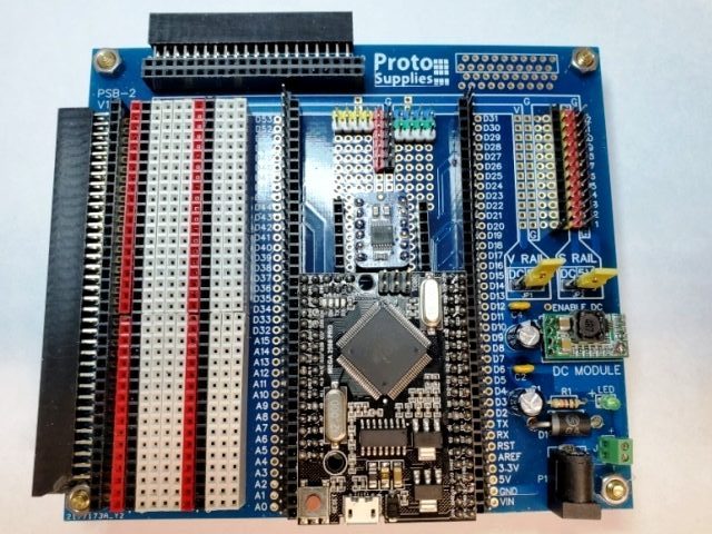
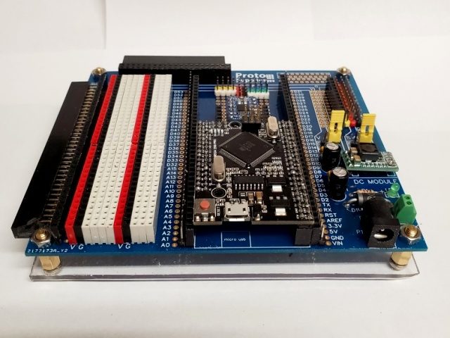
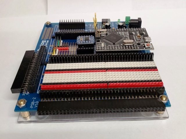
9/29/19 Mike H. shared his customized version of the Mega Breadboard. Mike primarily works with model train electronics but does some general hobby electronics as well and made some changes to adapt it towards his style of breadboarding.
For the solderless breadboard area, he soldered in single-row white, red and black female headers to make a permanent breadboarding area. The copper traces on the board take care of connecting the white rows and the red & black power/ground column runs.
On the top and left edge connectors, he went for maximum flexibility and strength by soldering in large double-row female right angle headers rather than using several smaller connectors or using single row connectors.
Mike put his logic level converter in a socket to make it easier to change out later if desired.
To protect the bottom, he mounted the board on a piece of acrylic with rubber bumpers.
He still plans to build a bracket to mount a dual voltmeter module attached to the acrylic base so that he can monitor the voltage on both power rails at all times.

You must be logged in to post a comment.