Counter For Reloading Ammo

We recently had a customer, Jeff, looking for a way to count the amount of ammo produced by his reloading equipment.
The manufacturer of the reloader equipment offers a counter that uses a mechanical switch to increment the count when you pull down the handle of the reloader. If the round doesn’t load properly, it will still count and the final count will be off. His goal was to have something that would count the ammo as it fell into the bin after it was successfully ejected by the reloader.
Looking for a solution, and with mechanics as his strong suit, Jeff reached-out to us for electronics guidance. I gave him a shopping list, and once purchased, I did the assembly and programming, since it was a fun and easy little project. I figured I would share it on our blog in case anyone else finds it useful. This basic setup is generic. You can use it in a number of different applications or expand on it in a number of ways.
Project Definition:
- Keep the scope of the project small so it can be complete in about half a day.
- Use a sensor that will be easy to mount into the final application.
- Provide a display to show the count.
- Include some buttons to clear the count or manually adjust the count if needed.
- Provide an audible indicator as to identify a count, so there is no need to watch the display.
- Assemble it to ship as a complete unit that will work out of the box, only requiring power plug-in.
Component list
With our project definition complete, we were able to create the list of part requirements.
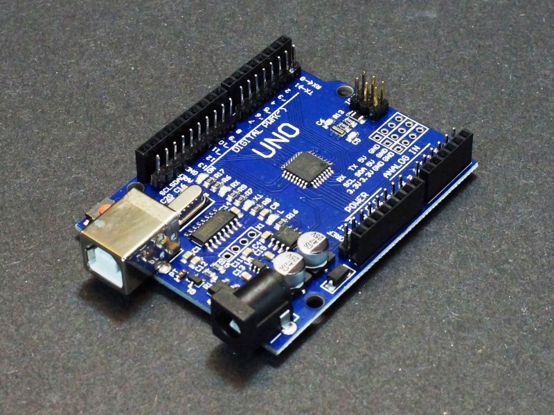
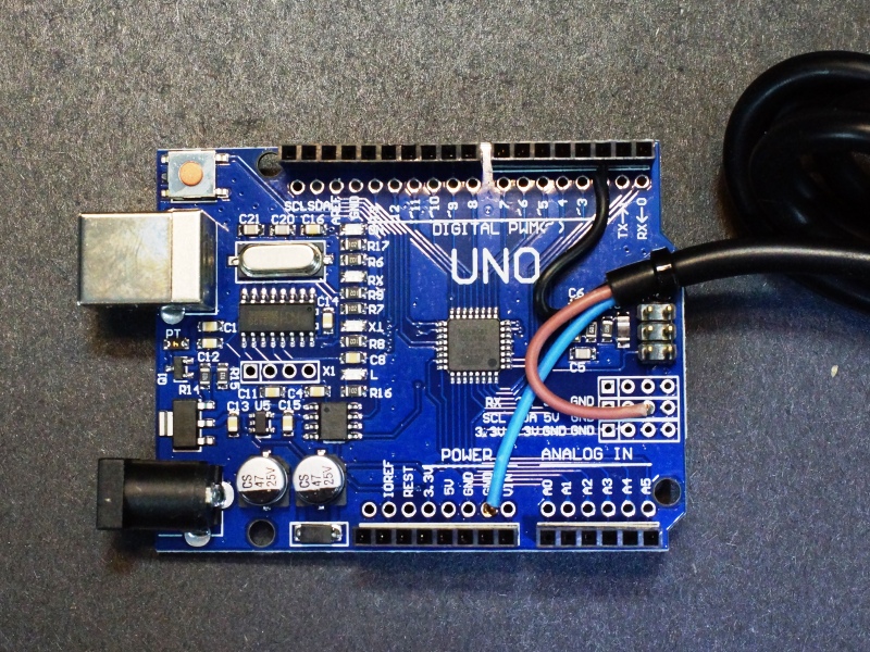
| $7.95 | For a microcontroller, the Uno R3 SMD was selected as it is inexpensive and will support a shield board.
The picture shows the optional male headers installed, but we didn’t use them for this project. |
 |
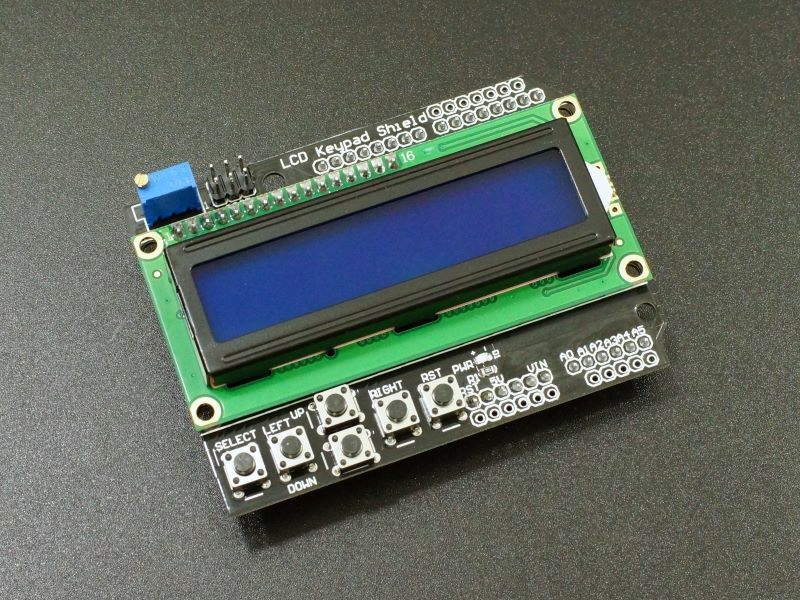
| $5.95 | For a display and buttons, the LCD1602 16×2 Blue LCD with Keypad Shield was an easy choice since it not only provided the display we needed, but it also includes some built-in buttons that we could use for thinks like clearing the display.
Since it is a shield, it stacks neatly on top of the Uno board. |
 |
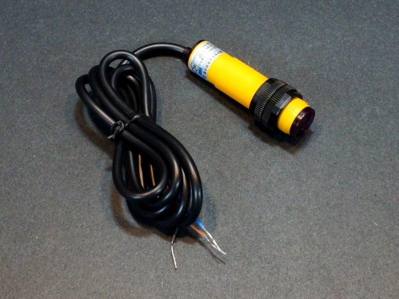
| $6.95 | For the sensor to detect the ammo, the E18-D80NK Infrared Proximity Sensor Module was selected.
These are nice industrial grade sensors that incorporate both an IR transmitter and receiver in the end of it. The sensor transmits an IR pulse at 490Hz and the receiver looks for it to bounce back off an object. The sensor detection range is adjustable from a couple of inches to a couple of feet. The round threaded-body and knurled-nuts allow for easy mounting through a round hole. A long attached cable allows mounting of the sensor and display up to 45″ apart, though easily extendable if needed. |
 |
| $1.49 | The E18-D80NK Proximity Sensor Mounting Bracket was included to provide a possible mounting option, but was not used in the final install. | 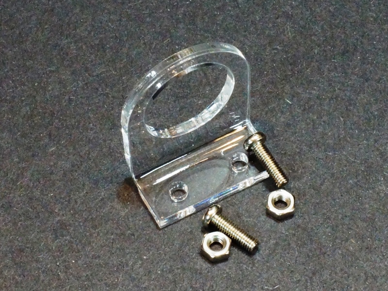 |
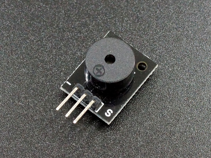
| $0.75 | For the audible feedback, we just went with a Passive Buzzer that we could send a tone to using PWM. By using PWM, we could adjust the frequency of the tone. Active buzzers tend to have an annoying note to them.
We did end up cobbling a transistor driver on the back of the module to increase the sound volume (a bit). |
 |
| $4.95 | For powering the setup, we used our AC Adapter 7.5V 1A wall bug.
These are really nice as the lower voltage puts less strain on the downstream 5V regulators. In this application it didn’t really matter. |
 |
| $1.49 | Lastly, we decided to put everything on an Uno and Breadboard Acrylic Base.
With this, we’re able to prevent any shorting-out should placement be on a conductive surface. This also allows the ability to drill for mounting and provides a handy spot for button labels. |
 |
| Incidentals for the buzzer driver. We used the same or similar parts out of our spare parts bins for this build. |
The Build
The actual build was very straightforward! We were able to borrow much of the code from our examples for each of the parts we did use. The little buzzer feature gave the most difficulty. In hindsight, while writing this post, I realize that a small design error got by me.
E18-D80NK Sensor
Since this was a dedicated application, we did solder the sensor pig-tail cable directly to the Uno board. We also added a strain relief using one of the mounting holes. The blue wire is going to Ground, the brown wire to 5V and the black wire, which is the sensor output, connects to digital pin 2. We chose Pin 2 because it has interrupt capability.
The E18-D80NK sensor output is normally HIGH and goes LOW when an object is detected. It stays low as long as it detects the object, so the interrupt is setup to trigger on the falling edge of the waveform.
The back of the sensor has a small screw which adjusts a potentiometer that sets the detection distance. Originally designed for counting objects moving on a conveyor belt, this feature is handy for adjustment to avoid seeing objects behind what you are targeting. For our application, we set the detection distance to give the shortest range possible which was about 1.5-2″, as to not see the operator or mechanical parts of the machine in its field of view.
Audible Buzzer
The buzzer sound output was too weak if driven directly off the Uno digital output. Also, it can draw more current from the output pin than is safe. The addition of a small driver circuit to the back of the buzzer was able to address both issues.
This driver consists of a small 2N3904 NPN transistor, 330 ohm current limiting resistor to protect the Uno pin and a 10uF filter capacitor. None of these component values are critical. The transistor can be any small NPN transistor, the resistor should work fine in the 330-1K range at least and the capacitor can be larger, but there is some space constraints. I didn’t bother testing a smaller cap to see if it would work, but it might.
Due to physical mounting considerations, we decided to power the circuit off the VIN rather than the 5V, which was our original intent. The power spike of the buzzer kicking-on caused an occasional power glitch, thus the addition of a filter capacitor at the buzzer to keep things happy.
In hind-sight, part of the problem was over-driving the buzzer with the increase of the operating voltage from 5V to over 7V. I should have added a small value series resistor on the buzzer power leg to lower the maximum current and to reduce any power-on voltage spikes.

We just soldered these extra components onto the backside of the module.
Using a couple of holes with solder pads, the buzzer module was soldered directly to the LCD shield board. The module was soldered to the VIN and Ground points. The 3rd pin, which is the signal input pin, was cut off and a blue wire routed through the hole and under the board to connect to the D3 pin on the other side of the shield. D3 was selected because it has PWM capability.

The buzzer is driven using the tone(pin, frequency, duration) command. I finally settled on 200Hz for 300mSec as being a decent ‘Beep’ sound that wouldn’t drive me crazy too quickly. I did add a pushbutton feature to turn the buzzer off – just in case it became annoying.
A bit on the loud side, for my taste, adding tape over the hole in the buzzer did dampen it to just about the right level. Again, lowering the current through the device would have been the better solution for lowering the volume.
LCD, Keypad & Mounting
The LCD uses a 4-bit parallel data bus to automatically connect to the necessary Uno pins when the shield is installed. Operation is fairly simple using the LiquidCrystal.h library.
The keys on the keypad connect to analog input A0 through the shield connections.
For those not familiar with this LCD w/ keypad, the keys are arranged in a voltage divider network using resistors, quite a novel technique. The output is then fed to the A0 analog input on the Uno. As you push the different buttons, the voltage divider, and therefore the output voltage, changes. By measuring the voltage against approximate voltage ranges, you can determine a button push and which button is pushed. While more complicated than simply using a digital input for each button, it does free up digital inputs which might be helpful in some applications.
The shield occupies the following pins on the Arduino with the rest being available for other uses. We use D2 for the sensor interrupt input and D3 for the buzzer output:
- D4 = LCD DB4
- D5 = LCD DB5
- D6 = LCD DB6
- D7 = LCD DB7
- D8 = RS
- D9 = LCD Enable
- D10 = Backlight Control
- A0 = Analog value of the button pushed
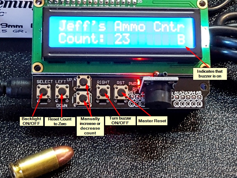
Some final touches; mounting the assembly on an acrylic Uno base in case it’s set on something conductive and to allow for drilling to mount on a wall. And not to be forgotten, the creation and addition of the button graphic. The graphic was created in MS Paint just to irritate my wife who does a lot of fancy graphics in Illustrator and thinks I am the only person left in the world crazy enough to still use MS Paint for some stuff.
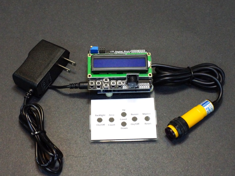
Here is a little better view of the functionality of the buttons and the display layout. Since there was an extra button, the ability to turn the backlight On & Off was added. The far right button is tied to the Reset of the Uno, taking everything back to the power-on state.
Below is the software created for this application.
Ammo Counter Application
/*
   Jeffs Ammo Counter Application

   Uses Uno, LCD shield and E18-D80NK  infrared module to implement a counter
   for ammo in a reloading station as it falls into a bucket.

   Note that there are some Serial.Println statements sprinked about.
    These are simply for debugging purposes.
*/
#include <LiquidCrystal.h>

// Define the pins used by the LCD panel.  These are fixed by the shield.
LiquidCrystal lcd(8, 9, 4, 5, 6, 7);

const int BTN_RIGHT = 0;
const int BTN_UP = 1;
const int BTN_DOWN = 2;
const int BTN_LEFT = 3;
const int BTN_SELECT = 4;
const int BTN_NONE = 5;
const int BACKLIGHT_PIN = 10;
const int OFF = 0;
const int ON = 1;

int lcd_key = BTN_NONE;
int adc_key_in = 0;
int backlight_state = ON;
int tone_on = ON;

int TonePin = 3;               // Pin connected to Passive Buzzer
int Freq = 200;                // Frequency to play buzzer at

unsigned int counter = 0;    // Holds the current count
unsigned int old_count = 0;  // Holds last count displayed

//===============================================================================
//  Initialization
//===============================================================================
void setup() {
  pinMode(TonePin, OUTPUT);

  Serial.begin(9600);
  lcd.begin(16, 2);              // Initialize LCD for 16 character x 2 line
  lcd.setCursor(0, 0);           // Position cursor to 1st col, 1st line
  lcd.print("Jeff's Ammo Cntr"); // print a message on the 1st line
  lcd.setCursor(0, 1);          // Position cursor 1st col, 2nd line
  lcd.print("Count: ");         // Print 'Count'
  lcd.setCursor(15, 1);         // Position cursor 15th col, 2nd line
  lcd.print("B");               // Print 'B' as buzzer is ON by default
  lcd.setCursor(7, 1);          // Position cursor to the count location

  digitalWrite(BACKLIGHT_PIN, LOW); // We set this pin LOW just once then set
  // to input or output to turn the backlight on/off

  attachInterrupt(0, Do_Count, FALLING);  // Create interrupt handler to count
  // pulses on falling edge of Int0 as sensor goes LOW when object is detected
}
//===============================================================================
//  Main
//===============================================================================
void loop() {
  if (counter > old_count) {    // Check the counter variable to see if interrupt
    Update_Count();             // handler incremented it. If so update display
  }
  lcd_key = Read_Buttons();    // read the buttons

  if (lcd_key != BTN_NONE) Do_Buttons();  // If a button is pressed, handle it
}

//===============================================================================
//  Subroutine - Increments the ammo counter when interrupt pin goes low
//===============================================================================
void Do_Count()
{
  counter++;  // increment the counter value
}

//===============================================================================
//  Subroutine - Updates the count on the display
//===============================================================================
void Update_Count()
{
  Serial.println (counter);
  lcd.setCursor(7, 1);
  lcd.print("      ");    // Clear current count space
  lcd.setCursor(7, 1);
  lcd.print(counter);     // Print new count
  old_count = counter;    // Set the old_count to our new count
  if (tone_on == ON) tone(TonePin, Freq, 300);  // If buzzer on, send tone
}

//===============================================================================
//  Read Buttons - Subroutine to read the ADC and return the button value
//===============================================================================
int Read_Buttons()
{
  adc_key_in = analogRead(0);      // read analog value from the button array
  // The buttons are connected to voltage divider that feeds into analog input A0
  // By looking at the voltage level, we can tell which button has been pressed
  // With no button pressed, the voltage will be pulled up to Vcc.
  if (adc_key_in >= 1000) return BTN_NONE; // Most likely result, so checked first
  if (adc_key_in < 50)   return BTN_RIGHT; // Work our way up the voltage ladder
  if (adc_key_in < 195)  return BTN_UP;    // And return first valid result found
  if (adc_key_in < 380)  return BTN_DOWN;
  if (adc_key_in < 555)  return BTN_LEFT;
  if (adc_key_in < 790)  return BTN_SELECT;

  return BTN_NONE;  // when all others fail, return this...
}

//===============================================================================
//  Do Buttons - Subroutine to act on the button pushes
//===============================================================================
int Do_Buttons()
/*
 * Note that we are using a delay(500) on the buttons to debounce them.
 * Since the buttons probably aren't going to be pushed while also using the
 * reloading machine, we don't expect this hard delay to cause any missed counts.
 */
{
  switch (lcd_key)
  {
    case BTN_RIGHT:   // Turns buzzer ON/OFF and sets a 'B' if it is ON
      {
        tone_on = (tone_on == ON) ? OFF : ON;
        Serial.println(tone_on);
        if (tone_on == ON) {
          lcd.setCursor(15, 1);
          lcd.print("B");
        }
        else {
          lcd.setCursor(15, 1);
          lcd.print(" ");
        }
        delay(500);     // Button debounce delay
        break;
      }
    case BTN_LEFT:      // Sets counter to zero
      {
        counter = 0;
        Update_Count();
        delay(500);     // Button debounce delay
        break;
      }
    case BTN_UP:        // Increments counter
      {
        counter++;
        Update_Count();
        delay(500);    // Button debounce delay
        break;
      }
    case BTN_DOWN:      // Decrements counter
      {
        if (counter > 0) {
          counter--;
          Update_Count();
          delay(500);    // Button debounce delay
        }
        break;
      }
    case BTN_SELECT:   // Toggles backlight ON / OFF
      {
        if (backlight_state == ON) {
          pinMode(BACKLIGHT_PIN, OUTPUT);
          backlight_state = OFF;
        }
        else if (backlight_state == OFF) {
          pinMode(BACKLIGHT_PIN, INPUT);
          backlight_state = ON;
        }
        delay(500);    // Button debounce delay
        break;
      }
    case BTN_NONE:
      {
        break;
      }
  }
}
Installation and Lessons Learned
Once the setup was complete, a cardboard mock-up chute and 9mm ammo drops were our functional tests. Everything worked perfectly in my simple test setup.
After shipment to the customer, he ran into a significant problem. The system was getting multiple counts per round on an almost continual basis. This of course defeats the whole purpose of the device.
Our customer took some pictures of the setup and I was able to locate a YouTube video of the same equipment in operation. I noticed immediately how tight the space was where the sensor needs to go. Specifically, how close to the sensor the handle and hand came while operating the machine. My first assumption was the sensor field-of-view was too big and it was seeing things other than just the passing ammo.
After a couple of emails and phone calls and some general brainstorming, I came to a different conclusion. The vigorous nature of the ejection of the ammo into the hard chute was causing the ammo to bounce aggressively. Since the sensor connects to a very fast interrupt input on the Uno, the ammo was moving in and out of its detection beam several times as it came into view of the sensor resulting in multiple counts.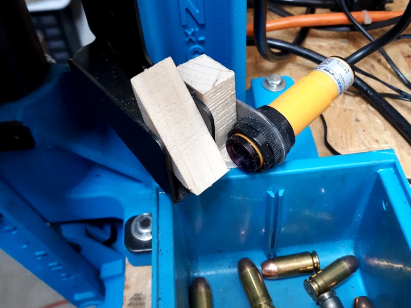
Fortunately Jeff has strong mechanical skills and was able to come up with a fix. A wedge block inserted in the chute helped settle the ammo before exiting the chute where the sensor was located. This is a picture of his prototype to verify the fix before building something more permanent. This feature will need to be able to be changed-out depending on the size of the ammo being reloaded.
The mistake I made in my testing was that my non-slick cardboard chute and easy ammo drop-down did not represent the true nature of how the ammo was actually being ejected. A more representative fixture would have caught this issue in my testing.
A possible design fix for the counter itself could be to add a bit of debouncing to the sensor interrupt counter routine. This could work since the ammo won’t be coming down the chute faster than a couple of seconds apart. Also, since this isn’t doing much other than waiting around for the sensor to be tripped and monitor the button status, the counting could probably be done using a polling scheme and debounced with something like a simple delay(500) statement to avoid multiple triggers on the same ammo.
What you can read next

3 Comments to “ Counter For Reloading Ammo”
You must be logged in to post a comment.
Great write up Ken. Thanks for your help. I will send you some pictures when I get it finalized.
I’ve been working on adding in a delay, but have not been successful, as a noob, where should I be looking to slow the possible readings down to 1 a second?
Brian, it is a little tricky because the program is using interrupts to detect when an object is detected and then increments a counter. This happens even if a delay(); is being used in the main loop.
If you just want to read the sensor only once every second, I would make the following basic changes:
1. Remove the interrupt by deleting attachInterrupt(0, Do_Count, FALLING);
2. Check if pin 2 which has the sensor attached is low in the main loop and if it is increment the counter. Something like
if (digitalRead(2)==LOW) counter++;
3. Delay program execution for 1 second by adding delay(1000); at bottom of the loop.
Main loop would look something like this
void loop() {
if (digitalRead(2)==LOW) counter++;
if (counter > old_count) { // Check the counter variable to see if interrupt
Update_Count(); // handler incremented it. If so update display
}
lcd_key = Read_Buttons(); // read the buttons
if (lcd_key != BTN_NONE) Do_Buttons(); // If a button is pressed, handle it
delay(1000);
}