Mega 2560 Pro with CH340 USB
$19.95
Fully compatible Mega 2560 for embedded applications.
25 in stock
Description
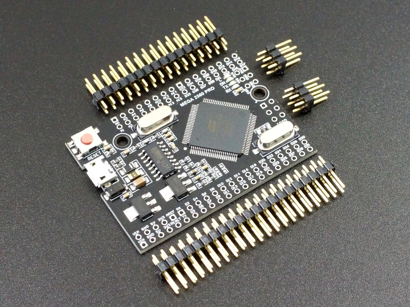
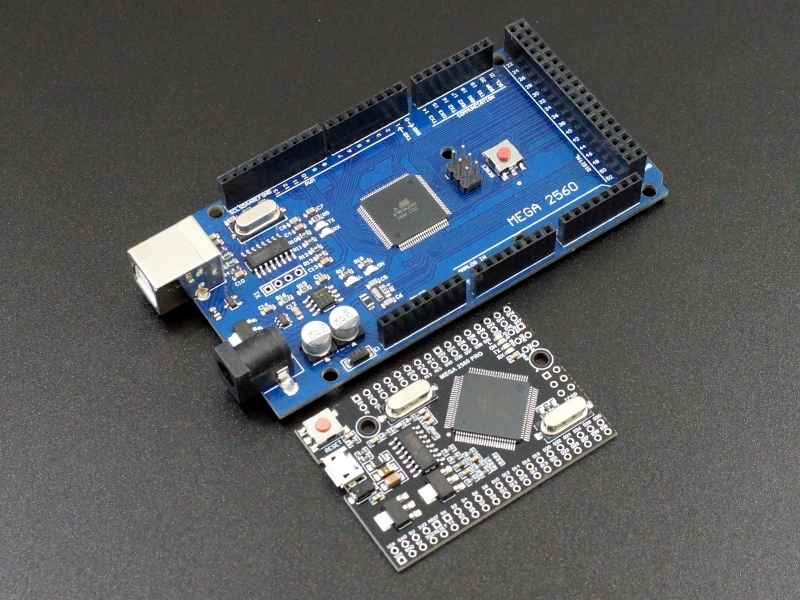
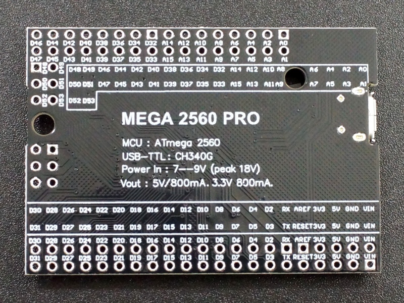
The Mega 2560 Pro with CH340 is compatible with the Arduino Mega 2560 but with a significantly reduced physical footprint for embedded applications. The Mega 2560 Pro provides a large amount of I/O and memory and is ideal for larger projects
Package Includes:
- Mega 2560 Pro with CH340 USB
- 2 x 16 male header
- 2 x 21 male header
- 2 x 3 (x2) male header
Key Features of MEGA 2560 PRO with CH340 USB:
- ATmega2560 processor running at 16MHz
- CH340 Serial to USB converter
- 256KB Flash memory
- 54 Digital I/O
- 15 PWM shared with the digital I/O
- 16 Analog inputs that can also be used as digital I/O for a total of up to 70 digital I/O
- 4 Hardware serial ports
- Small form factor with all pins on 0.1″ centers for universal prototype board compatibility.
- 5V Operation
To compress the Mega 2560 into the smaller package of the Pro version, the DC power connector was deleted, the large USB connector was changed to a micro USB and the I/O pins are doubled up. Functionally the board is fully compatible with the standard Arduino Mega 2560.
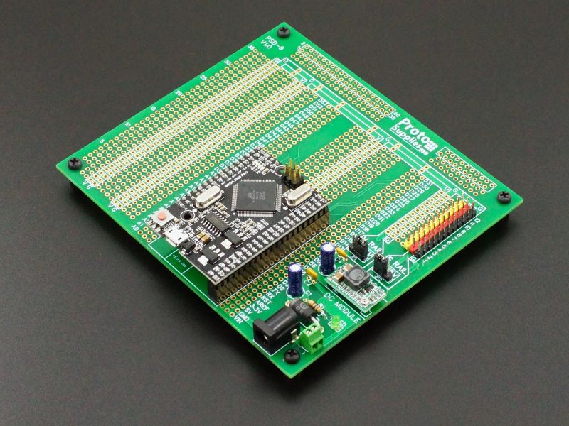
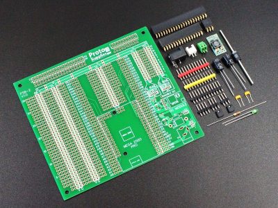
The male header pins are all on 0.1″ centers and if mounted on the bottom the board will fit on a standard 0.1″ style perf board for point-to-point wiring. If the headers are mounted on top, then female jumpers can be used for making breadboard style connections. A better option for some users is our Mega 2560 Pro MCU Proto Board available down below. This board mounts the Mega 2560 Pro MCU module and brings all the I/O out for easy connection. It has a flexible power input section and even provides a DC-DC converter to power Servo motors and the like.
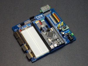
We used it to create a flexible breadboarding and test setup as shown below.
Click on the pic above for a blog post on building that type of setup.
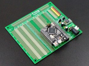
Click the pic for full Mega 2560 Pro MCU Proto Board information. PCB available as PCB only without the component kit, with component kit, kit fully assembled and fully assembled with the Mega 2560 Pro preinstalled. Click Add To Cart to select which option you want.
The Mega 2560 Pro operates internally at 5V. The board can be powered directly off the USB connection or an external power supply in the range of 7 – 12V can be connected to the VIN pins. On-board 5V and 3.3V regulators provide 5V and 3.3V outputs.
The board can also be powered by applying 5V to the 5V pins. This bypasses the on-board regulators and and should only be used if a stable 5V power source is available.
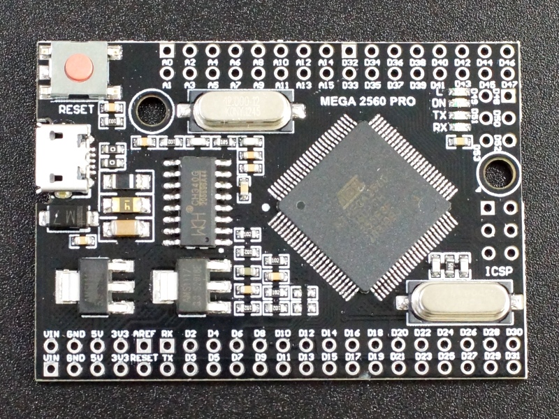
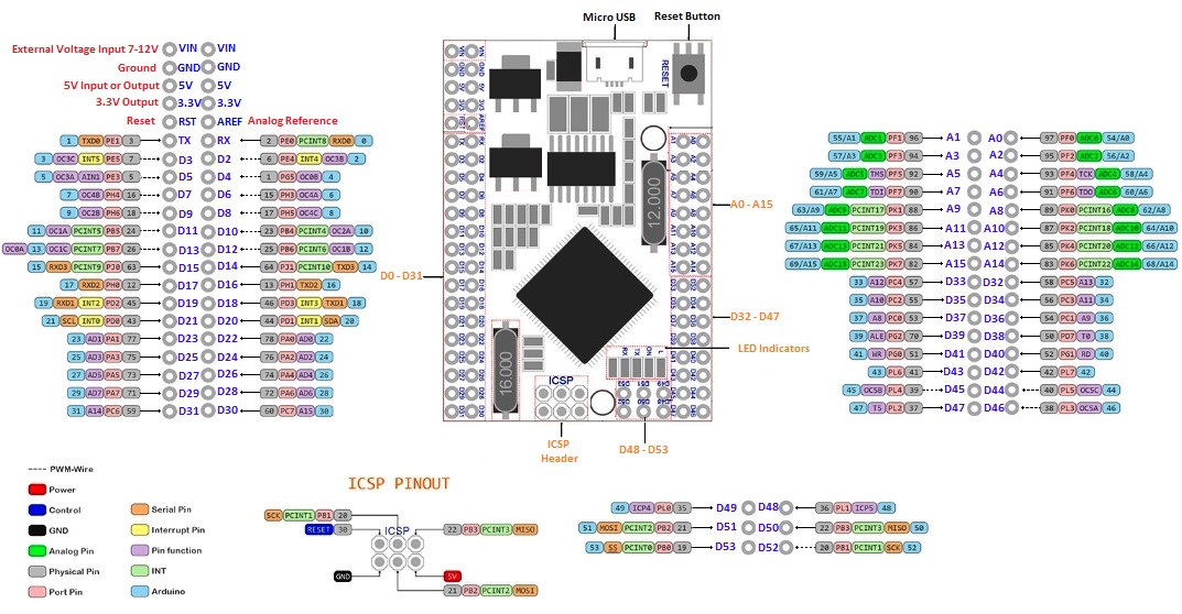
The attached Mega 2560 Pro board pin-out shows the most commonly used functions for the pins, but some pins can support other functions. Though the pinout locations are different, the basic pins and their functions are identical to the normal Mega 2560.
To program the board using the IDE, select the normal Mega 2560 as the board type.
Assembling the Board
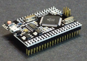
Assembled Mega 2560 Pro Module
The board ships with the male headers loose. This provides flexibility and allows the headers to be soldered to either the top or bottom of the board depending on planned usage.
In some cases, it may be preferable to directly solder wires to the solder pads instead. Female headers can also be used instead of the male headers if desired.
To ensure good alignment when using with a universal prototype board or the Mega 2560 Pro MCU Proto Board, it is best to insert the headers into the proto board while the headers are being soldered to the mega 2560 Pro to ensure the headers are held straight during the soldering process.
Our Evaluation Results:
These are nice assemblies with good build quality.
The compact size, large I/O count and plug-in nature of these boards makes them ideal for some types of projects, especially where you want to permanently embed the board into the project. When coupled with our Mega 2560 Pro MCU Proto Board, it makes for a very flexible platform for larger projects.
The board uses the CH340 chip for USB communications. If you have any issues with connecting to the board, you may need to download a driver. Just search for Arduino CH340 driver and you will find a number of sources for drivers depending on what Windows or Mac operating system you are using.
Before they are shipped, these modules are:
- Blink downloaded to verify basic operation
- Repackaged into resealable ESD bag.
Further Reading:
Additional Info on Arduino.cc website
Notes:
- None
Technical Specifications
| Microcontroller | ATmega2560 | |
| Serial to USB Converter | CH340 | |
| Operating Voltage | 5V | |
| Input Voltage (recommended) | 7-12V | |
| Digital I/O Pins | 54 | |
| PWM I/O Pins (Shared with Digital I/O) | 15 | |
| Analog Input Pins (can also be used as digital I/O) | 16 | |
| DC Current per I/O Pin | 20mA | |
| DC Current which can be drawn from 3.3V Pin | 50mA | |
| Flash Memory | 256 KBytes | |
| SRAM | 8 KBytes | |
| EEPROM | 4 KBytes | |
| Clock Speed | 16MHz | |
| Built-in LED | Attached to digital I/O Pin 13 | |
| USB Connector Style | Micro-B Female | |
| Board Dimensions (PCB) | 54 x 38mm (2.1 x 1.5″) | |
| Country of Origin | China |
You may also like…
-
Select options This product has multiple variants. The options may be chosen on the product page
Mega 2560 Pro MCU Proto Board
$7.95 – $51.95Mounts Mega 2560 Pro MCU Module for building projects
Select PCB Only, PCB With Kit, Fully Assembled, Assembled with Mega 2560 Pro

