Mega 2560 Pro MCU Proto Board-Blue
$7.95 – $12.95
Mounts Mega 2560 Pro MCU Module for building permanent projects
Select Board Only or Board With Component Kit
Description
Note: This version of the board with blue solder mask has been replaced with the version with green solder mask and is no longer available. The two boards are identical other than the color.
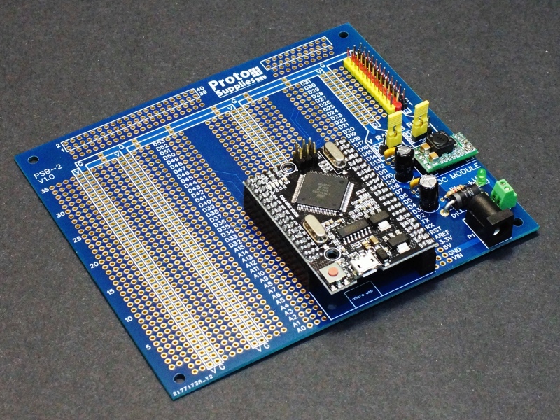
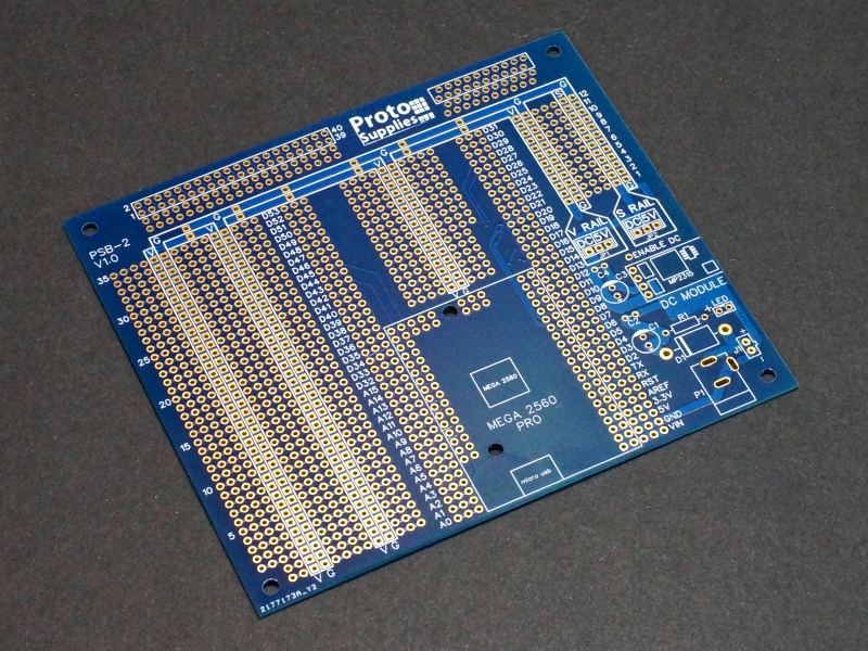
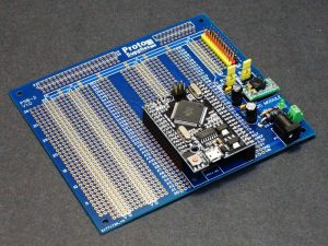
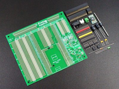
This quality board is part of our custom Pro Series boards and is specifically designed to mount the Mega 2560 Pro module. The board provides flexible options for input power and power distribution including a built-in DC-DC converter module. Available as board only or with an optional component kit to build the base system and mount the Mega 2560 Pro MCU module.
This is the same board as the green version, just with a blue solder mask. We are phasing the blue boards out, so get them while you can!
PACKAGE INCLUDES:
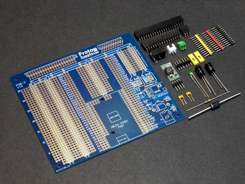
- Mega 2560 Pro MCU Proto Board – Blue
- Optional Components Kit (Click links for more details on components or to buy separately)
- Qty 1 – DC Power Jack
- Qty 1 – JST XH-2.54 2-pin connector
- Qty 1 – Screw terminal, 2-pin
- Qty 1 – 1N5822 Schottky Reverse Polarity Protection Diode 40V/3A
- Qty 2 – 100uF 25V electrolytic bulk filter capacitor
- Qty 2 – 0.1uF ceramic bypass capacitor
- Qty 1 – 3mm green power LED
- Qty 1 – 1Kohm LED current limiting resistor
- Qty 2 – 1×3 male header with jumpers for optional MCU 5V or DC-DC converter output
- Qty 3 – 1×12 Red/Yellow/Black male headers for Servo rail
- Qty 1 – MP2315 DC-DC Module with 1×4 header
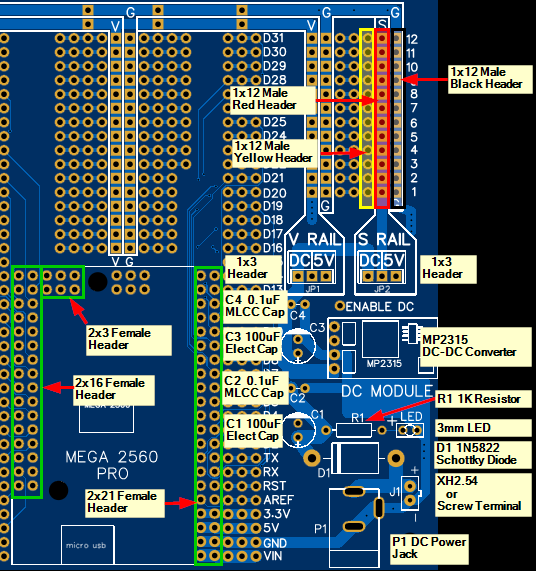
- Qty 1 – 2×3 Female header for Mega 2560 Pro Socket
- Qty 1 – 2×16 Female header for Mega 2560 Pro Socket
- Qty 1 – 2×21 Female header for Mega 2560 Pro Socket
KEY FEATURES OF MEGA 2560 PRO MCU PROTO BOARD:
- Female header socket to mount Mega 2560 Pro module
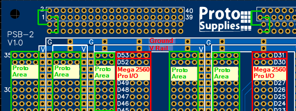
- All Mega 2560 Pro I/O brought out to 3-hole pattern for making connections
- Flexible DC input power options
- Built-in DC-DC converter module to power separate power rail for servo motors or can power entire power rail
- Fully distributed power and ground with clear silkscreen top and bottom
- Standard 0.1″ / 2.54mm hole pattern prototyping areas with extra large plated through holes and pads
- High quality construction with ENIG (Electroless Nickel Immersion Gold) finish
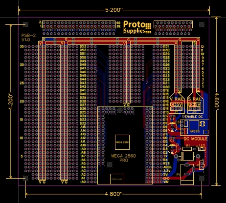
- Board dimensions are 5.2″ x 4.6″
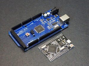
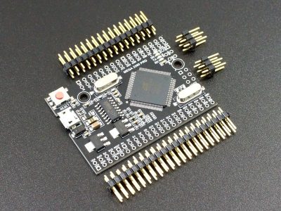
The Mega 2560 Pro MCU module is great in concept since it packages the popular Arduino Mega 2560 with its large amount of I/O and larger memory into a small form factor that can be permanently embedded into a project. Unfortunately it has been difficult to use this module in practice due to its double row of I/O pins on 3 sides.
Our Mega 2560 Pro MCU Proto Board is specifically designed to make it easy to use the Mega 2560 Pro to build permanent projects that can make use of the larger amount of I/O and extra memory that the Mega 2560 Pro module has available over modules like the Arduino Nano or Micro Pro. It includes a flexible power input and distribution setup including a build-in DC-DC converter module for powering servos or circuits that require a different or isolated operating voltage.
Power Input Options
The DC power input section of the board has several different input connector options
It can mount a standard DC power jack in location P1 and a JST XH-2.54 style 2-pin battery connector or a small 2-pin screw terminal with 2.54 lead spacing for connecting to bare wires in 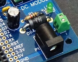
The board is clearly marked to make correct hookup easy.
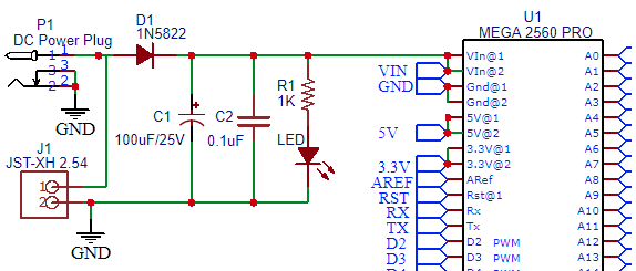
The main input power has a reverse polarity protection diode in location D1. Our optional component kit includes a beefy 1N5822 Schottky diode that can handle up to 3A continuous current with a small voltage drop of only around 0.3V (typical). A standard 1N4001 or similar diode can be used if the larger voltage drop and 1A current limitation is not a problem for the application. The large 0.059″ D1 mounting holes will also accept larger gauge solid wire up to 16 AWG if no input diode is desired to avoid any voltage drop.
This input section has locations for an electrolytic filter input filter capacitor C1 with 2.54mm lead spacing, a ceramic bypass capacitor C2 with 2.54mm lead spacing as well as a 3mm power on LED with current limiting resistor R1. Be sure to observe the correct polarity on the electrolytic capacitors and LED during installation.
The optional component kit includes all three connectors and 100uF/25V electrolytic caps, 0.1uF bypass ceramic caps, a 3mm green power LED and a 1K LED current limiting resistor for populating this section of the board.
Note: With the white JST XH-2.54 style connector, the power and ground pin assignment may vary depending on the cable that is being plugged into the connector since these pins are not standardized. You may need to reverse the connector when inserting it into the board to match up with the power source or you can re-pin the wires on the female connector to match the board.
Power Distribution
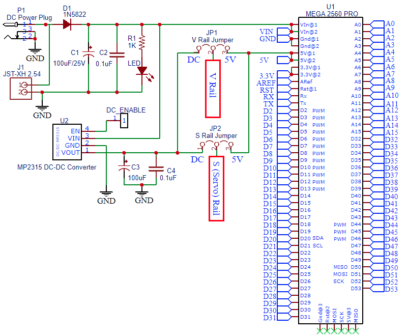
The main input power is connected to the VIN input pin on the Mega 2560 Pro MCU module when it is installed. The MCU module is always powered by the on-board 5V regulator to ensure it gets the cleanest power possible and to provide another level of protection for the MCU.
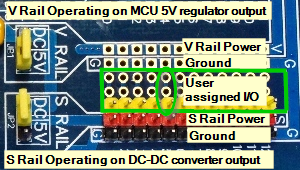
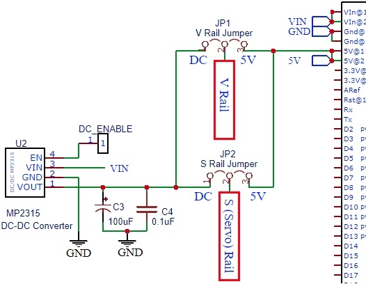
The 5V output of the on-board MCU regulator is brought out to the V Rail and S Rail power selection jumpers and is labeled 5V on the board.
The main input power is also connected to the input of the MP2315 DC-DC Converter Module (if it is used) which is described below. The output of this DC-DC converter module is also brought out to the V Rail and S Rail jumpers and is marked DC on the board.
The V Rail is the main voltage supply rail that covers most of the board. The S Rail is the small section of power power rail on the right side of the board. The S Rail is mainly designed as a Servo power rail or other dedicated power rail though it can be set to be the same power as the V Rail.
The V Rail jumper – JP1 determines the power source to use for the main voltage supply Rail. If it is jumpered to 5V the rail will be powered by the 5V output of the MCU module. If it is jumpered to DC, it is powered by the DC-DC converter and will be whatever voltage the DC-DC converter is adjusted to.
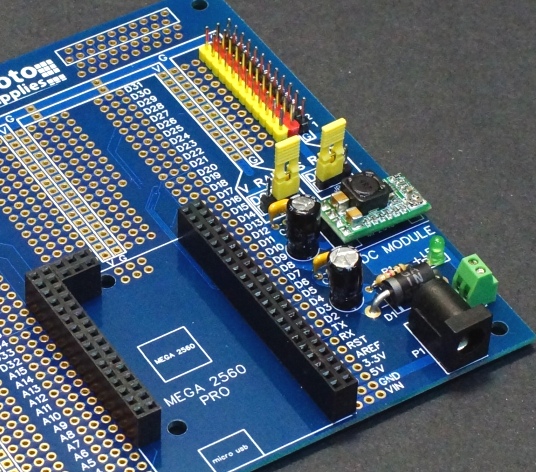
The S Rail jumper – JP2 determines the power source to use for the S(ervo) Rail. If it is jumpered to 5V the S Rail will be powered by the 5V output of the MCU module. If it is jumpered to DC, it is powered by the DC-DC converter and will be whatever voltage the DC-DC converter is adjusted to. Yellow, red and black headers are included which can be optionally installed on the S Rail to allow easy connection of 3-pin servo motors or 3-pin sensors.
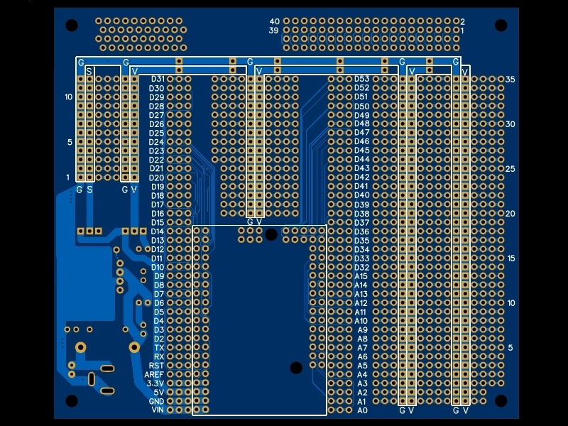
All power and ground rails are silk-screened on both sides of the board and the power and ground pads are square to further clearly differentiate them.
The distributed adjacent power and ground runs allow for easy placement of additional bypass or filter caps as needed if the board is used to mount high speed / high current circuits.
Built-in DC-DC Converter Module
The board has a spot to mount an MP2315 DC-DC Step Down Converter Module.
These super compact MP2315 modules provide up to 2A peak and 1.5A continuous current and are adjustable over the range of 0.8V up to within about 0.6v of the input voltage. If the input 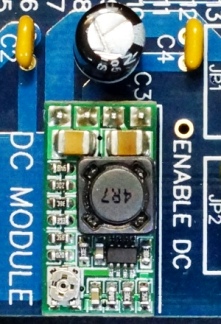
The MP2315 modules also have the feature of being able to add a solder bridge to the back of the module to program it to output a fixed voltage such as 3.3V or 5.0V which is handy if you don’t need the adjustability. Just be sure to set the voltage before soldering the module in place. The module can also be mounted in a 1×4 female header to make it removable if more flexibility is desired.
This DC-DC converter module can be used to power Servo motors and provide isolation from the rest of the logic circuits from the electrical noise of the motors. The output noise and ripple of this module is clean enough that it can also be used as a power source for the main power rail on the board to power logic circuits and sensors if servo motors are not being used. It is also a handy way to create 3.3V for sensors that require that power source.
The output of the DC-DC converter can be controlled by the MCU if desired. A solder pad next to the DC-DC converter labeled “ENABLE DC” can be pulled low using an output pin on the MCU to disable the converter output. This enable input has a pull-up resistor on the DC-DC converter module to enable the output of the module by default.
The output of the DC-DC converter section has locations for an electrolytic filter capacitor C3 with 2.54mm lead spacing and a ceramic bypass capacitor C4 with 2.54mm lead spacing if it is desirable to add some additional output filtering.
The optional component kit comes with the MP2315 DC-DC Converter and 4-pin male header for soldering it to the proto board as well as a 100uF electrolytic and 0.1uF ceramic capacitor to populate this section. You may want to pick up a 1×4 female header if you want to socket this part instead of soldering it to the board.
Click for more info on the DC-DC converter module.
Mega 2560 Pro Socket
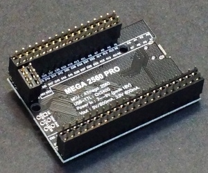
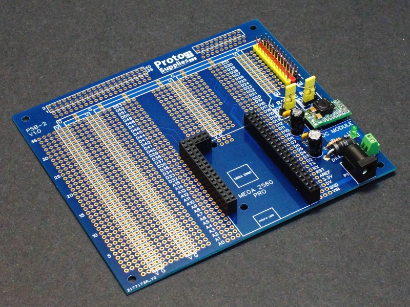
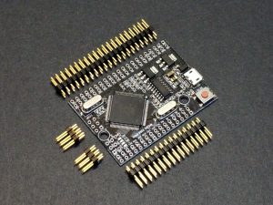
Female headers installed on Mega 2560 Pro MCU Module Male Pins
The board uses three double-row female headers to create a socket for the Mega 2560 Pro MCU module.
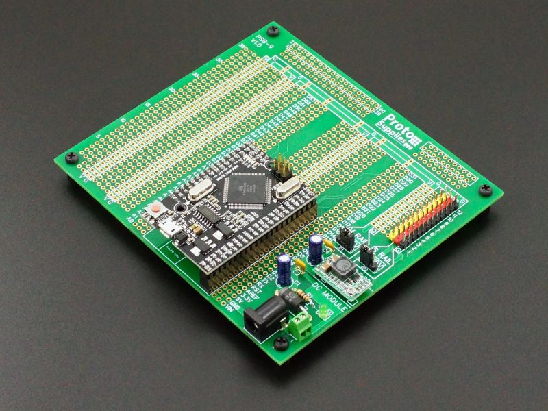
With these sockets soldered in place as shown down below, every pin on the Mega 2560 Pro MCU module is brought out to 3-hole patterns that run the length of the board on either side of the MCU module. This allows three solder connection points for each I/O pin. Each of the pins is clearly labeled with the basic pin name such as D32 or A15.
In some cases, it may be useful to populate one of the three holes with single-row of female headers like found on a standard Mega 2560 which will allow breadboard jumpers to be used with the module.
The optional component kit comes with the correct size double-row female headers (2×3, 2×16, 2×21) to form the socket. Optionally larger double-row female headers can be carefully cut down to the length required to create the socket.
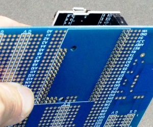
Insert into Mega 2560 Pro MCU Proto board for soldering
When soldering the female headers, it is highly recommended to install them on the Mega 2560 Pro MCU module male headers first and then insert that into the proto board for soldering.
That will help insure that all the pins will line up and the MCU module can be easily inserted and removed from the socket.
The Mega 2560 Pro MCU board can of course be soldered directly to the proto board instead of using sockets if desired, though once soldered don’t expect to get it back off… ever…..
Note: The ICSP connector is footprinted on the proto board, but the pads do not connect to anything. Normally a male header is soldered to the ICSP pads on the top of the MCU board, but if it is desired to tap these pins on the proto board, a 2×3 female header can be added to the proto board and the male header can be soldered to the bottom of the Mega 2560 Pro MCU module to mate with it.
[enh_ajax_add_to_cart_button product=7289 show_price=a]
Flexible Prototype Areas
Besides the Mega 2560 Pro socket and corresponding 3-hole connection pads, the rest of the prototyping area uses a 3-hole or 4-hole pad patterns with interleaved power and ground runs for connecting discrete components, DIP ICs and SMD components mounted on SMD to DIP adapter boards.
The back edge of the board has a 2 x 20 header area with separate solder pads for connecting wires as well as a 2 x 10 area with offset pads that can be useful for some types of connectors that use offset pins such as RJ45s or single row headers can be used in these locations.
All holes are large 40 mil plated through with large 70 mil pads. These are large enough to use with TO-220 type package pins.
The 3-hole and 4-hole patterns have 30 mil traces connecting them on both the top and bottom of the board for good current handling capability.
Optional Component Kit
The optional component kit includes all the parts needed to completely populate the core portion of the board. These are the parts we provide, but similar value parts out of your parts bin can also be used.
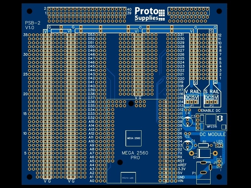
DC input section includes:
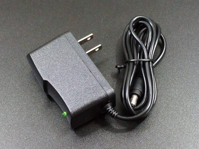
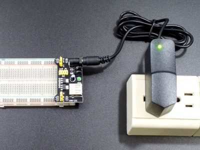
- P1 – DC power jack for use with a standard AC wall adapter.
- J1 – JST style XH2.54mm header typically used for connecting to a battery and a 2-pin screw terminal for connecting to bare wires. Install one or the other.
- C1, C2 -100uF electrolytic filter and ceramic 0.1uF bypass capacitors
- D1 – Beefy 1N5822 Schottky reverse polarity protection diode. This can be replaced with a suitable wire if it is desired to not having any voltage drop through the diode. This is approximately 0.3V.
- R1 – 1K ohm 1/4W current limiting resistor for the LED
- LED – 3mm green LED. The shorter lead is the cathode, so the longer lead should be oriented to the anode ‘+’.
DC-DC converter section includes:
- MP2315 2A DC-DC converter
- 1×4 male header for mounting the converter
- C3, C4 – 100uF electrolytic filter and ceramic 0.1uF bypass capacitors on the output of the DC-DC converter
Power distribution section includes:
- 1×3 male headers and jumpers for the V Rail and S Rail power source selection.
- 1×12 strips of yellow, red and black headers for making 3-pin servo or sensor headers (Signal/Power/Ground) on the S Rail.
Mega 2560 Pro socket includes:
- 2×3 gold female header
- 2×16 gold female header
- 2×21 gold female header
Locations for the components can be found below.
High Quality Finish
The boards are constructed of 1.6mm FR-4 with 1oz copper and blue solder mask.
The copper has an ENIG (Electroless Nickel Immersion Gold) finish for maximum performance. ENIG ensures extended shelf life against corrosion, provides excellent solderability with lead or lead-free solder and provides a completely flat soldering surface. It is also fully ROHS compliant.
Board Mounting
The board is 5.2 x 4.6″. It has four 0.138″ diameter holes which can accept up to 3.5mm or #6 screws. The holes are spaced 4.8 apart on long side and 4.2″ apart on short side
Projects Using This Board
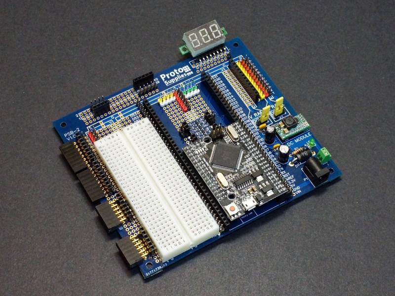
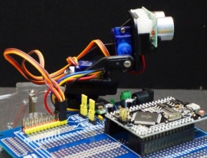
For an interesting solderless breadboard / test platform idea using this board, check out our Mega Breadboard blog post.
Notes:
- None
Technical Specifications
| Material | FR-4 | |
| Copper | 1 oz, double-sided | |
| Plating | ENIG (Electroless Nickel Immersion Gold) | |
| Solder Resist | Blue | |
| Silkscreen | Front and Back | White |
| Prototype Area | Holes, plated-thru | 1.02mm (0.04″) |
| Pads | 1.78mm (0.07″) | |
| Dimensions | Board outline | 132 x 106.7mm (5.2 x 4.6″) |
| Board thickness | 1.6mm (0.062″) | |
| Mounting holes | 3.5mm (0.138″) | |
| Mounting holes center-center | 121.9 x mm (4.8 x 4.2″) |
You may also like…
-
Select options This product has multiple variants. The options may be chosen on the product page
Mega 2560 Pro MCU Proto Board
$7.95 – $51.95Mounts Mega 2560 Pro MCU Module for building projects
Select PCB Only, PCB With Kit, Fully Assembled, Assembled with Mega 2560 Pro

