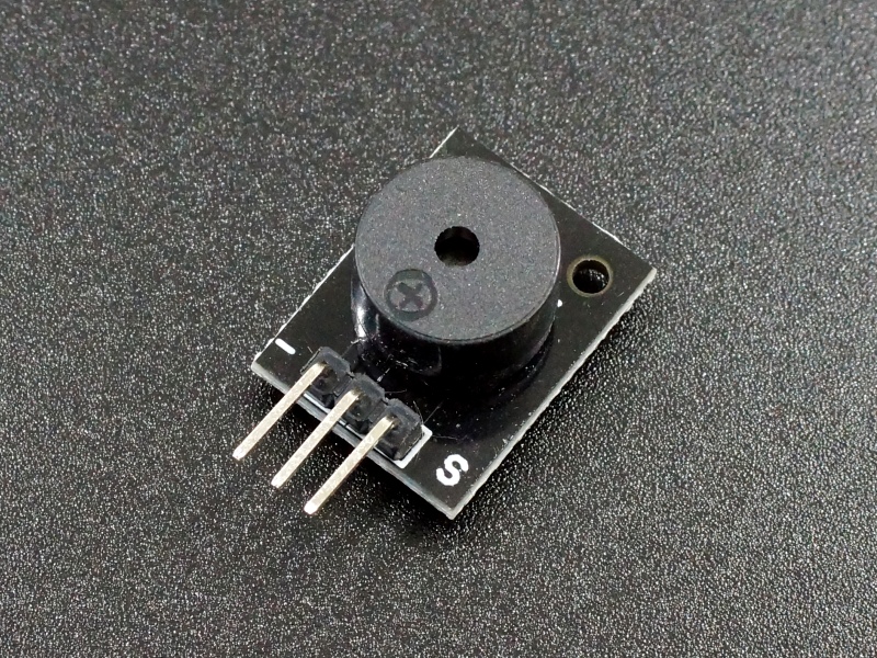
Buzzer Passive 5V Module
$0.79
Passive piezo buzzer module for creating sound in a project.
50 in stock
Description
This is a passive piezo buzzer module useful for creating sound in a project.
PACKAGE INCLUDES:
- Buzzer Passive 5V Module
KEY FEATURES OF BUZZER PASSIVE 5V MODULE:
- Uses passive buzzer that needs to be driven by a PWM signal.
- 5V operation nominal. The signal can range from 0-5V in practice.
There are two types of buzzers, passive buzzers such as this one and active buzzers.
Passive buzzers are similar in function to a small speaker and need to be driven by a waveform with enough drive current capability to create the desired sound. This is typically done using PWM from an MCU. The advantage of a passive buzzer is that the tone and loudness of the buzzer can be controlled by the frequency and drive power of the waveform that is used to drive it.
By contrast active buzzers have the drive circuitry built into them, so a simple logic level signal will activate the buzzer. Though simpler to use, the downside of the active buzzer is that the tone of the buzzer is fixed at a particular frequency and the loudness is more or less fixed. Active buzzers are mainly useful for signaling or an alarm.
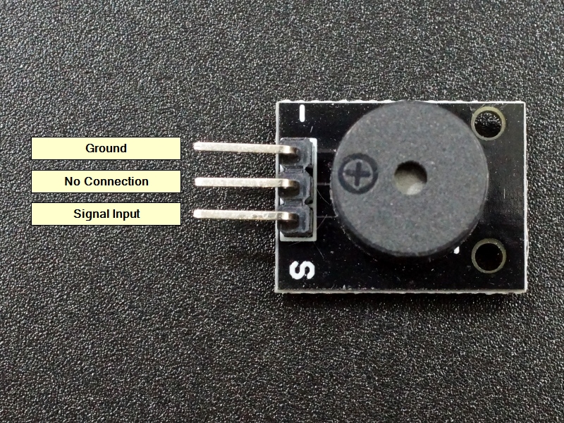
Module Connections
There is a 3-pin header on the assembly.
1 x 3 Header
- ‘-‘ = Ground
- Center pin = No connection
- S / ‘+’ = Signal input, connects to digital output on MCU
Note: The location of the ‘-‘ and ‘S’ pins may be reversed compared to the picture shown. Passive buzzers are not polarity sensitive and will work even if the leads are reversed. The ‘S’ pin may also be labeled as ‘+’.
The buzzer has an impedance of approximately 15 ohms. If driving it using an MCU output pin which is typically limited to about 20-40mA max before damage may occur, a series resistor of at least 120 ohms should placed between the digital output pin on the microcontroller and the buzzer to limit the current and avoid damage.
If driving from an MCU pin without any amplification, the sound will be fairly quiet. If a louder sound is desired, a transistor or other amplifying device can be placed in-circuit to provide a stronger drive to the buzzer.
OUR EVALUATION RESULTS:
These modules are useful for learning the basics of driving a small speaker with an MCU using PWM, but it’s not going to replace your home stereo system by any stretch of the imagination. For a better sound reproduction, you may want to look at one of our small speakers as shown below.
Here is a little ditty played off an MCU using this buzzer.
The below code snippet shows the basics of getting some noise out of the buzzer using the tone(Pin, Freq); command on an Arduino.
Remember to connect a 120 ohm or larger resistor between the output pin and the buzzer to avoid possible damage to the Arduino. You will also need to attach the ground pin to the Arduino ground.
Buzzer Passive 5V Module Test Program
/*
Exercise Passive Buzzer

Basic code to step through several frequencies on a buzzer to test operation.
*/

int TonePin = 6;               // Pin connected to Passive Buzzer
int Freq = 500;                // Frequency to play buzzer at

// the setup function runs once when you press reset or power the board
void setup() {
   pinMode(TonePin, OUTPUT);      // Buzzer
}

// the loop function runs over and over again forever
void loop() {
 tone(TonePin,Freq);            // Send tone to buzzer

  delay(1000);                  // wait for 1 Sec
  Freq = Freq + 500;            // Increment tone by 200 Hz
  if (Freq > 4000) Freq = 500;  // Go up to 4KHz then restart back at 500Hz
}
BEFORE THEY ARE SHIPPED, THESE MODULES ARE:
- Inspected
- Sample tested per incoming shipment
- Packaged in a resealable ESD bag for protection and easy storage.
Notes:
- This module is similar to or the same as the KY-006.
Technical Specifications
| Maximum Ratings | ||
| Drive Signal | 0 – 5V | |
| IMax | Maximum Current Draw with buzzer impedance of ~ 15 ohms | ~ 333mA |
| with 125 ohm series resistor (140 ohms total) | 36mA | |
| Dimensions | L x W (PCB) | 19mm x 15mm (0.75 x 0.60″) |
| Country of Origin | China |


