Teensy 4.x Audio Adapter
$14.75 – $18.75
Add 16-bit 44.1kHz sample rate (CD quality) audio to Teensy 4.x projects.
Select No Pins, Pins or Pins and Mic
Description
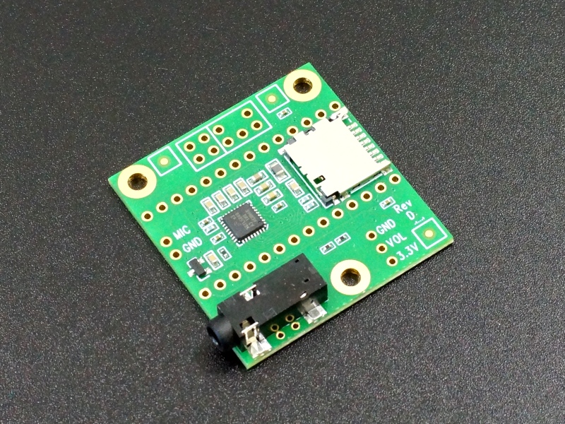
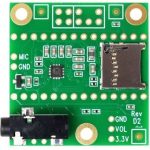
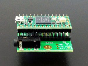
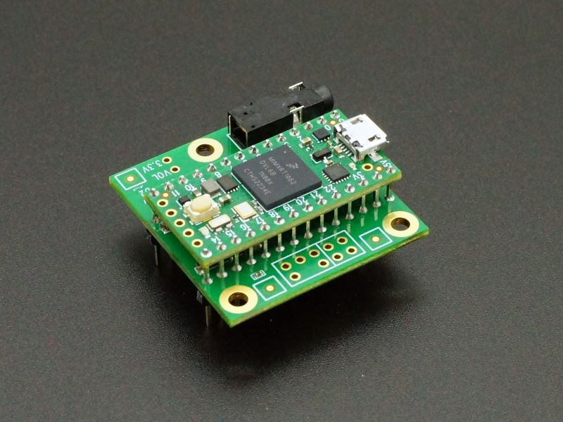
The Rev D or D2 Teensy Audio Adapter lets you add high quality 16-bit 44.1kHz sample rate (CD quality) audio to your projects. It is compatible with the Teensy 4.0 and 4.1 products.
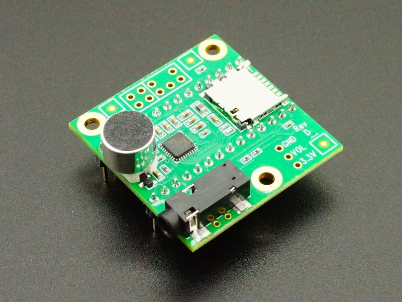
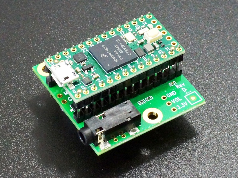
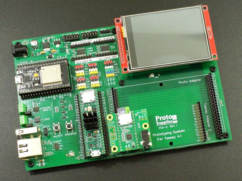
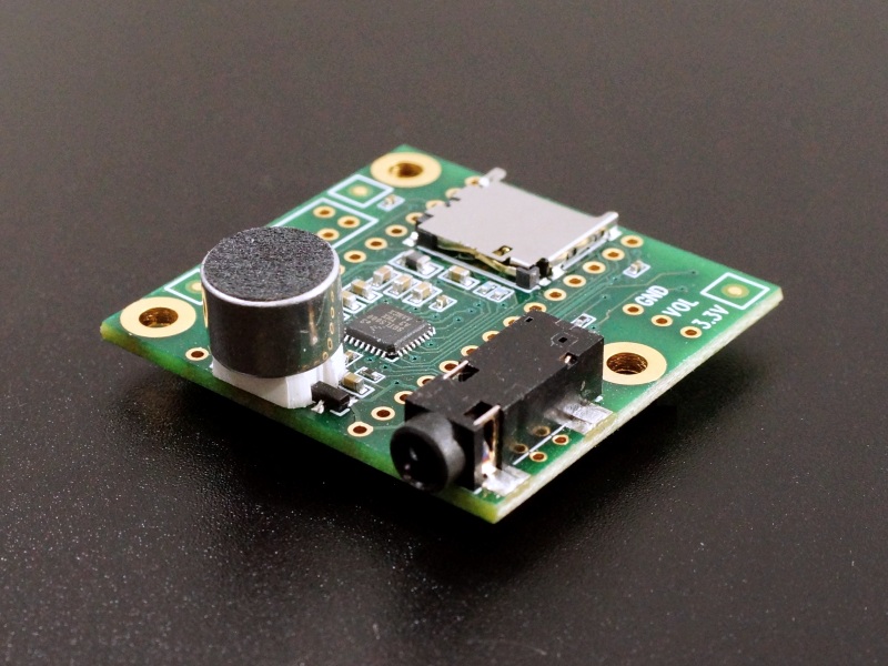
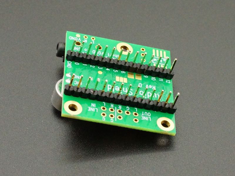
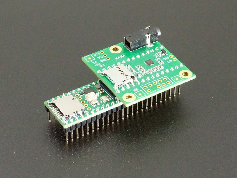
We also offer versions with gold male header pins and gold male header pins and microphone pre-installed to allow the Audio Adapter to plug into our Prototyping System and Project System for Teensy 4.1 baseboards. Due to the wide PCB board width, the Audio Adapter will not work with a solderless breadboard unless U-Shaped type jumpers are inserted before the Audio adapter is installed. The pinned versions can be used to stack on top of a Teensy 4.0 or Teensy 4.1 if female headers are installed on those boards.
Package Includes:
- Teensy 4.x Rev D or D2 Audio Adapter
- Male header pins and microphone optionally soldered on
KEY FEATURES OF TEENSY 4.x Rev D Audio Adapter:
- 16-bit, 44.1kHz sample rate audio
- Plays uncompressed WAV and Raw audio files
- 4-channel software mixer
- 3.5mm audio jack
- Micro-SD card slot
- Supports stereo line-level or mono microphone input
- supports stereo headphone and stereo line-level output
- Utilizes I2C bus for control
- Utilizes I2S audio for data
- Small size is perfect for embedding.
- 3.3V operation
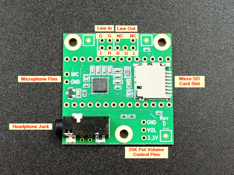
The adapter supports stereo headphone and stereo line-level output as well as stereo line-level input or mono microphone input.
The board uses the SGTL5000 stereo codec IC that includes a headphone amplifier. The board also comes with a 3.5mm audio jack for headphones, a micro-SD card slot for storing audio files and optional spaces for a 25K volume control potentiometer, microphone and Flash memory chip.
The Teensy Audio Library is installed with Teensyduino. It lets you use the input and output simultaneously together with a toolkit of audio processing objects to easily create sophisticated audio applications. You can play multiple sound files, create synthesized waveforms, apply effects, mix multiple streams, and output high quality audio to the headphones or line out pins.
The Teensy 4.x microcontroller boards have the Cortex-M7 DSP instruction set that provides the computational power for real-time FFT (spectrum analysis), opening up the possibility of creating advanced sound-reactive projects.
The Teensy product line which is focused on being fast , small and Arduino compatible is developed by the company PJRC. They have a loyal following of designers and advanced hobbyists that create many libraries to take advantage of some of the more advanced features of the Teensy products or to modify Arduino libraries for compatibility. Many of them also participate in the excellent PJRC forum. The forum is targeted towards more advanced users and topics and includes a category for Audio Projects many of which utilize these these adapters.
Note: We are starting to ship the new Rev D2 Audio Adapter. This was created by PJRC due to a shortage on the SD Card holder and the SGTL5000 chip which required a change to a smaller 20-pin package. The D2 is functionally the same as the Rev D except it does not have solder pads to select a different I2C address.
We do not differentiate between the two versions and may ship either version.
Getting Started with Teensy Audio Adapters
Adapter Connections
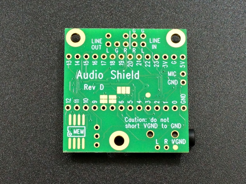
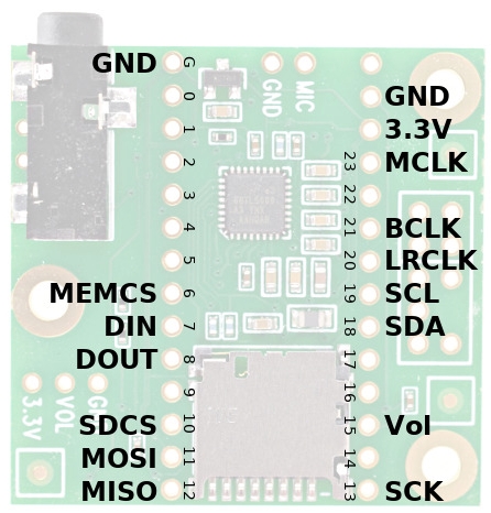
The Audio Adapter connects to Teensy through two 1×14 headers using the signals as shown in the table below. Shareable indicate pins can also be used by other devices that use the same bus type.
| Function | Teensy 4.x Pins | Shareable |
| Audio Data | 7, 8, 20, 21, 23 | |
| Audio Control | 18, 19 | SDA, SCL (other I2C chips) |
| Volume Pot | 15 (A1) | |
| SD Card | 10, 11, 12, 13 | MOSI, MISO, SCK (Other SPI Chips) |
| Memory Chip | 6, 11, 12, 12 | MOSI, MISO, SCK (Other SPI Chips) |
Recommended Memory Chips (optional)
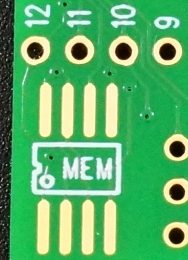
The board has space for a 128M-bit (16MB) Flash memory with SPI interface.
The Teensy Audio Library can play audio clips from this memory using the SerialFlash library.
This Flash memory has a much lower access latency than SD cards which allows many sounds to be played simultaneously.
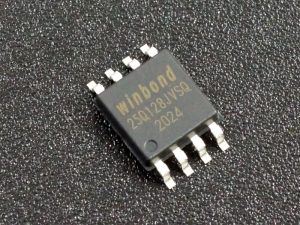
The following Flash chips are compatible.
- W25Q128JV
- W25Q128FV
If you are adding a Flash memory chip to the adapter, it is easiest to solder it before adding any headers to the board, though adding it later is not too difficult with a small tip soldering iron.
Click the pic for full Flash information.
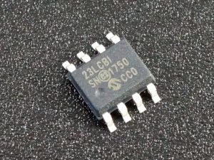
Alternatively, a 1M-bit (128kB) SRAM with SPI interface may be used. The Teensy Audio Library can use the RAM chip for a multi-tap delay line of up to 1.5 seconds. This demo video shows the delay feature in operation.
The following devices are compatible.
- 23LC1024
Click the pic for full SRAM information.
If using a memory chip, it is easiest to solder it on before any headers are added to the board for easiest access. Be sure to observe the correct polarity of the part while mounting. The white dot denotes pin 1.
Recommended Volume Control Potentiometer (optional)
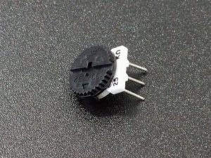
The board has a location for a 25K thumbwheel potentiometer to optionally provide a manual volume control or to control another audio parameter if desired. The potentiometer feeds Teensy pin 15 ( Analog input A1) so can be used as a generic control input.
You can find the link to the full potentiometer information by clicking on the pic.
Recommended Microphone (optional)
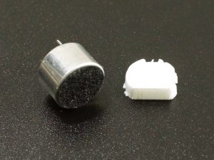
The board has a location for a microphone to optionally provide an microphone input on the board. The microphone is included on the boards that have pins installed for use with the Prototyping System for Teensy 4.1
You can find the link to the full microphone information by clicking on the pic.
Recommended SD Cards (optional)
Most SD cards are optimized for sequential access for use in devices like cameras, so all will work fine for playing a single WAV file at a time.
For simultaneous playing of 2-4 stereo WAV files, you need to use an SD card optimized for non-sequential access. PJRC recommends SanDisk Ultra for this application.
The Arduino SD library supports up to 32GB. Do not use larger 64 or 128GB cards.
The Audio Library includes a simple benchmark to test SD cards. Open it from File / Examples / Audio / HardwareTesting / SdCardTest.
Mounting the Audio Adapter
The Audio Adapter typically mounts as a shield on either the top or bottom of the Teensy board. If the Audio Adapter is mounted on top, it gives better access to the microphone input and volume potentiometer if they are used. If the adapter is mounted under the Teensy, it provides easier access to the Teensy Programming button. Depending on the mounting method used, you may want to solder on some wires to remotely mount these items. If mounting to the larger form factor board such as the Teensy 4.1, the connectors will be offset to the USB end of the board. When used with our Prototyping System for Teensy 4.1 baseboard, it can be plugged into either of the two adapter slots.
If the Audio Adapter is mounted next to the Teensy and wires run between them such as on a solderless breadboard, keep the wires as short as possible to minimize audio artifacts such as popping.
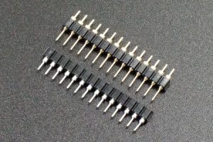
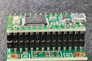
Permanent Install – Stack and solder together
This technique uses special double-insulator male headers that allow the boards to be stacked and permanently soldered together. This setup does allow the assembled module to be plugged into a breadboard.
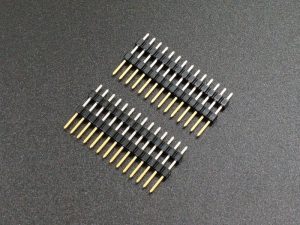
Header Male 1×14 Double Insulator 2-Pack
Removable Install – Stack with Male / Female headers
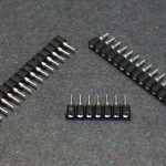
In this case the top board gets standard 1×14 male headers installed on the bottom and the bottom board gets standard 1×14 female headers installed on the top (or vise versa). Our machined headers can be snapped to length and can be used as one option for this type of mounting.
 HDR-27-G - Header Machined Round Pin Male 1×40 Break-away Gold$0.95 Qty HDR-27-G - Header Machined Round Pin Male 1×40 Break-away Gold$0.95 Qty Max: 100 Min: 1 Step: 1 ADD TO CART |
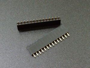
If you want to make the whole assembly breadboard compatible or have the option to mount a third board, you can use stackable female headers on the bottom board or put standard female headers on the bottom of the top board and use a male header with extra long pins on both sides on the bottom board.
Our Evaluation Results:
The Teensy line of boards are an excellent product that provides high performance and advanced I/O to tackle even the hardest problems which is why they are often found in advanced hobbyist projects as well as low volume production builds.
The PJRC forum provides access to excellent technical advice that is far more advanced than found on the normal Arduino forums. It is the best place to find information on how to use the advanced features found in the Teensy. It is not the place to get basic Arduino type questions answered however, which is good as the forum is not cluttered with ‘how do I blink an LED?’ type questions.
It is highly suggested to checkout the PJRC website and forum at the links below for additional information.
Before they are shipped, these modules are:
- Inspected and tested by PJRC
- Packaged in high quality resealable ESD bag for safe storage.
Further Reading:
PJRC Audio Forum – Excellent source of technical information
PJRC website – Audio Adapter Boards – Good source of additional info
PJRC Audio Tutorial – Parts, manual and videos for getting started with the Audio Adapter boards.
Notes:
- None
Technical Specifications
| I/O Logic Levels | 3.3V |
| Operating Voltage | 3.3 picked up from Teensy board. Re-regulated to 1.8V for SGTL5000 |
| Typical Operating Current | 16mA typical, 50-60mA max with SD card and full headphone volume. |
| Board Dimensions (PCB) | 35x 37mm (1.4 x 1.5″) |
| Country of Origin | USA |
| Mfr | PJRC |
| Datasheet | SGTL5000 Datasheet |
You may also like…
-
Select options This product has multiple variants. The options may be chosen on the product page
Teensy 4.x Audio Stacks
$45.95 – $55.95For compact Teensy 4.0 and 4.1 audio projects

