Audio Workshop 6
Mixers and Playing Multiple Sounds
The previous tutorial showed how to configure an audio system to play a single sound. In this tutorial, we will be using mixers to combine multiple sounds.
Adding Mixers to Our Current Design
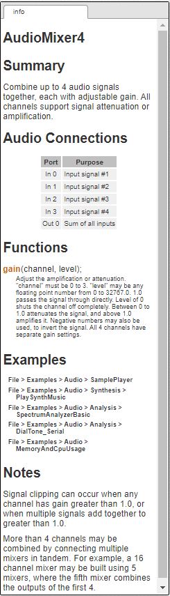
A mixer is an object that takes 1 to 4 inputs and combines them into one audio stream on the output. They have programmable gain on each of the inputs, so channels can be mixed in different ratios or can be turned off by setting their gain to 0, allowing the mixer to behave like a switch that switches between different inputs.
In the Audio System Design Tool, find the mixer object in the list on the left and click on it.
When you click on any object, the right-side panel updates with documentation for that object.
Most objects have functions which you can call from your Arduino sketch to configure or change what the object does. For the mixer, each input channel has an adjustable gain. these can be set once, or changed at any time. In this section we’ll use the gain() function to switch or fade between 2 songs. the design tool serves as a handy reference manual when you write your code.
To add the mixers to the previous example, first click on the two wires that connect the objects in the canvas so they are highlighted in orange and hit delete to remove them.
Now drag a second playSdWav object onto the canvas.
Also drag two of the mixer objects onto the canvas. Arrange the objects and draw wires to connect the objects as shown below. The exact positioning of the objects doesn’t matter. Sometimes, offsetting the objects somewhat so the wires don’t overlap allows the wire connections to be more obvious.
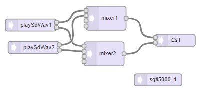
Each playSdWav object has 2 outputs for left and right channels. mixer1 combines both left channels and connects to the left channel input of i2s1. mixer2 similarly combines both right channels and connects to the right channel input of i2s1.
The design tool allows you to easily compose complex audio systems. Every object you place on to the canvas continuously processes CD quality sound. Each wire causes a stream of digital (44.1kHz, 16-bit) audio to automatically flow between 2 objects.
Turn the Design into Code and Use it in a Program
Copy and paste the program below into a window on the IDE.
// Advanced Microcontroller-based Audio Workshop
//
// Part 2-2: Mixers & Playing Multiple Sounds
//
//  ProtoSupplies.com Changes and Additions:
//    Change pin #s to match tutorial adapter to avoid conflicts
//    Initialize, but don't use LCD in this example
#include <ILI9341_t3.h>
#include <font_Arial.h>
#include <XPT2046_Touchscreen.h>


///////////////////////////////////
// copy the Design Tool code here
///////////////////////////////////


// Use these with the Teensy Audio Shield
#define SDCARD_CS_PIN    10
#define SDCARD_MOSI_PIN  7
#define SDCARD_SCK_PIN   14

// Use these with the Teensy 4.1 SD card
//#define SDCARD_CS_PIN    BUILTIN_SDCARD
//#define SDCARD_MOSI_PIN  11  // not actually used
//#define SDCARD_SCK_PIN   13  // not actually used

// LCD control pins defined by baseboard
#define TFT_CS 40
#define TFT_DC  9

// Use main SPI bus MOSI=11, MISO=12, SCK=13 with different control pins
ILI9341_t3 tft = ILI9341_t3(TFT_CS, TFT_DC);

// Touch screen control pins defined by baseboard
// TIRQ interrupt if used is on pin 2
#define TS_CS  41
//#define TIRQ_PIN  2
XPT2046_Touchscreen ts(TS_CS);  // Param 2 = NULL - No interrupts
//===============================================================================
//  Initialization
//===============================================================================
void setup() {
  Serial.begin(9600);

   // Setup LCD screen
  tft.begin();
  tft.setRotation(3);
  ts.begin();
  ts.setRotation(1);
  tft.fillScreen(ILI9341_BLUE);

  AudioMemory(8);
  sgtl5000_1.enable();
  sgtl5000_1.volume(0.5);
  SPI.setMOSI(SDCARD_MOSI_PIN);
  SPI.setSCK(SDCARD_SCK_PIN);
  if (!(SD.begin(SDCARD_CS_PIN))) {
    while (1) {
      Serial.println("Unable to access the SD card");
      delay(500);
    }
  }
  pinMode(24, OUTPUT); // LED on pin 24
  mixer1.gain(0, 0.5);
  mixer1.gain(1, 0.5);
  mixer2.gain(0, 0.5);
  mixer2.gain(1, 0.5);
  delay(1000);
}
//===============================================================================
//  Main
//===============================================================================
void loop() {
  if (playSdWav1.isPlaying() == false) {
    Serial.println("Start playing 1");
    playSdWav1.play("SDTEST1.WAV");
    delay(10); // wait for library to parse WAV info
  }
  if (playSdWav2.isPlaying() == false) {
    Serial.println("Start playing 2");
    playSdWav2.play("SDTEST4.WAV");
    delay(10); // wait for library to parse WAV info
  }
  // uncomment this code to allow Knob VR2/A3 to pan between songs
/*
  int knob = analogRead(A3);  // knob = 0 to 1023
  float gain1 = (float)knob / 1023.0;
  float gain2 = 1.0 - gain1;
  mixer1.gain(0, gain1);
  mixer1.gain(1, gain2);
  mixer2.gain(0, gain1);
  mixer2.gain(1, gain2);
*/
}
Next, as in the previous tutorial, Export the design you just created in the Audio System Design Tool and copy and paste the code it generates into the program in the section “copy the Design Tool code here”.
Verify and Upload the completed program to the Teensy. You should now hear a jumble of music, with 2 songs of different genres being mixed together and playing simultaneously.
This code near the end of setup() is responsible for the not-so-pleasing mashup of these dissimilar songs.
  mixer1.gain(0, 0.5);
  mixer1.gain(1, 0.5);
  mixer2.gain(0, 0.5);
  mixer2.gain(1, 0.5);
This is the gain() function we saw documented in the design tool. In this example, each channel is set to a gain of 0.5 (half volume). If both signals happen to be at their maximum of +1.0 or -1.0 signal level, by using 0.5 gain, the worst case is adding together to 1.0 or -1.0
Signals should always be between -1.0 to 1.0. If you mix signals to a sum beyond 1.0, the result is limited or “clipped” to 1.0. Clipping causes harmonic distortion. Gains are usually set to prevent clipping. As an added exercise, try adjusting the gains to something higher to experience clipping distortion. Much of the practical experience of audio design is familiarity with the sounds caused by common mistakes. Be sure to reset the gains back to 0.5 when finished.
Implement Fading by Calling the gain() Function in loop()
Near the end of the program is a section of code to uncomment. It will allow the VR2/A3 knob on the right to adjust the mixer gains as both songs play allowing you to fade from one song to the other. As the gain of one mixer is increased, the gain of the other mixer is decreased. Many objects can be put to creative uses like this by calling their functions from Arduino code while they’re processing live audio.
  // uncomment this code to allow Knob VR2/A3 to pan between songs
  int knob = analogRead(A3);  // knob = 0 to 1023
  float gain1 = (float)knob / 1023.0;
  float gain2 = 1.0 - gain1;
  mixer1.gain(0, gain1);
  mixer1.gain(1, gain2);
  mixer2.gain(0, gain1);
  mixer2.gain(1, gain2);
In the next tutorial, we will show how to play samples (short sound clips) from Teensy memory rather than using an SD card.