Audio Workshop 5
First Audio System Design Tool Use
The Teensy Audio Library is very powerful with great flexibility, but with that power and flexibility also comes complexity. Fortunately the PJRC team has created a graphical audio design tool that dramatically simplifies specifying an audio system.
The previous code examples had collections of audio objects which we have not covered. In this section, we’ll explore how to use the Design Tool to create your own audio systems.
Using the Audio System Design Tool Interface
To run the Design Tool, open a web browser and go to https://www.pjrc.com/teensy/gui/
The blank canvas in the middle is where the design is created by dragging and dropping audio objects and linking them together.
On the left side is a list of all the audio objects grouped into functional categories such as Input, Output, Mixer and Synth. On the right side is the documentation for the selected object.
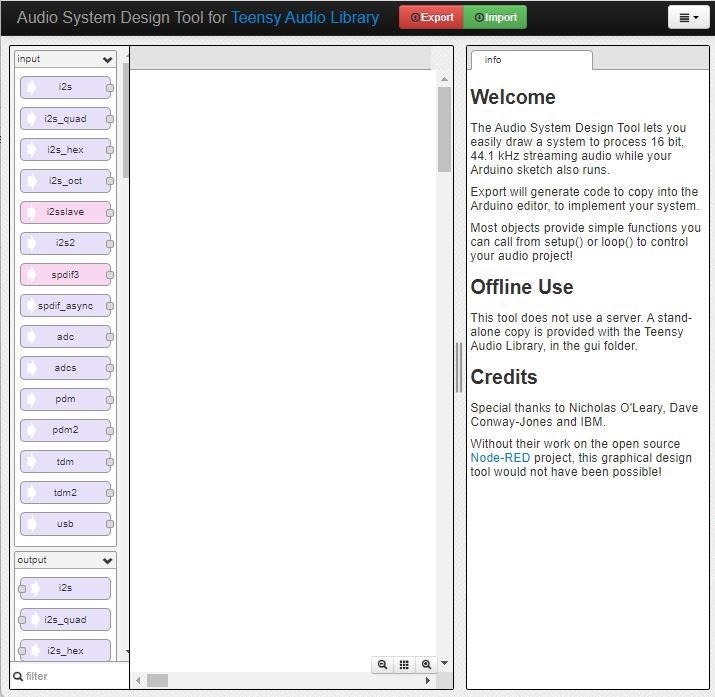
Designing the Audio System We Have Been Using
In this tutorial, we will create the audio system setup that we have been using in the examples so far.
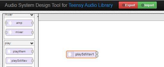
Objects are grouped by type. Scroll down the left panel until you get to the section titled “play“. In the play section is playSdWav which stands for Play SD card WAV file. If you hover the mouse over the objects, an informational popup opens to provide more information about the object.
Click and drag this object to the upper left area of the canvas. Note that a “1” is automatically appended to the object. This is to differentiate it if more than one of the same object is added to the system.
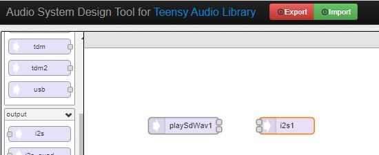
Next locate the i2s object in the “output” section. Drag the i2S object onto the canvas to the right of the playSdWav object.
The i2s object sends digital audio data from the Teensy to the Teensy Audio Adapter. i2s (short for Inter-IC Sound) is the technical name for a data bus for signals which communicate digital stereo sound.
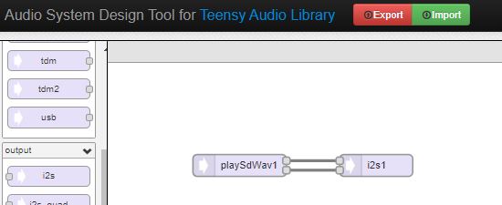
Now we need to connect these objects together. Click and hold on their small squares which indicate an input or output and drag your mouse to draw wires for the signal paths. Each wire causes a stream of 16-bit 44.1kHz audio data to automatically flow between the objects. since this is stereo, we will draw two wires in parallel for a left and right channel.
One more object needs to be added to control the Audio Adapter. Scroll down to the end of the object list to “control” and drag the sgtl5000 object onto the canvas. The sgtl5000 is the audio chip on the Audio Adapter. this is a special hardware control object, which does not have audio connections, but must be present to control the Audio Adapter hardware.
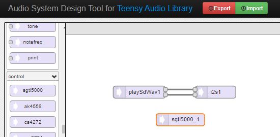
That completes the design of our simple audio system. Now lets make use of it.
Turn the Design into Code and Use it in a Program
Copy and past the program below into a new window on the IDE. It will look very similar to our previous examples, but it is missing the audio system configuration information.
// Advanced Microcontroller-based Audio Workshop
//
// Part 2-1: First Desogm Tool Use
//
// WAV files for this and other Tutorials are here:
// http://www.pjrc.com/teensy/td_libs_AudioDataFiles.html
// These files are included on the SD card shipped with Fully Loaded baseboards.
//
//  ProtoSupplies.com Changes and Additions:
//    Change pin #s to match tutorial adapter to avoid conflicts
//    Add touchscreen LCD support
//    Show WAV file playing on LCD

#include <ILI9341_t3.h>
#include <font_Arial.h>
#include <XPT2046_Touchscreen.h>


///////////////////////////////////
// copy the Design Tool code here
///////////////////////////////////


// Use these with the Teensy Audio Shield
#define SDCARD_CS_PIN    10
#define SDCARD_MOSI_PIN  7
#define SDCARD_SCK_PIN   14

// Use these with the Teensy 4.1 SD card
//#define SDCARD_CS_PIN    BUILTIN_SDCARD
//#define SDCARD_MOSI_PIN  11  // not actually used
//#define SDCARD_SCK_PIN   13  // not actually used

// LCD control pins defined by baseboard
#define TFT_CS 40
#define TFT_DC  9

// Use main SPI bus MOSI=11, MISO=12, SCK=13 with different control pins
ILI9341_t3 tft = ILI9341_t3(TFT_CS, TFT_DC);

// Touch screen control pins defined by baseboard
// TIRQ interrupt if used is on pin 2
#define TS_CS  41
//#define TIRQ_PIN  2
XPT2046_Touchscreen ts(TS_CS);  // Param 2 = NULL - No interrupts
//===============================================================================
//  Initialization
//===============================================================================
void setup() {
  Serial.begin(9600);

   // Setup LCD screen
  tft.begin();
  tft.setRotation(3);
  ts.begin();
  ts.setRotation(1);
  tft.fillScreen(ILI9341_BLUE);

  AudioMemory(8);
  sgtl5000_1.enable();
  sgtl5000_1.volume(0.5);
  SPI.setMOSI(SDCARD_MOSI_PIN);
  SPI.setSCK(SDCARD_SCK_PIN);
  if (!(SD.begin(SDCARD_CS_PIN))) {
    while (1) {
      Serial.println("Unable to access the SD card");
      delay(500);
    }
  }
  delay(1000);
}
//===============================================================================
//  Main
//===============================================================================
void loop() {
  if (playSdWav1.isPlaying() == false) {
    Serial.println("Start playing");
    playSdWav1.play("SDTEST3.WAV");
    delay(10); // wait for library to parse WAV info
    tft.setCursor(10, 120);
    tft.setFont(Arial_10);
    tft.println("Start playing:  SDTEST3.WAV");
  }
  // do nothing while playing...
}
Fortunately, we just created the necessary missing information to complete the program. In the Design Tool, click the red Export button. The Design Tool will create the code needed to operate the system you just designed and show it in a popup window.
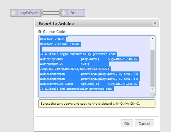
The code will already be highlighted, so just Ctrl-C to copy and then paste into your program where it says “copy the Design Tool code here”.
Verify and Upload the completed program to the Teensy. The program is the same basic song player from Workshop 2, but this time you created the audio objects that allow it to function.
Playing one stereo WAV file can be very useful in projects, but we can do much more with the tools at our disposal. In the next tutorial, we will look into using mixers to combine sounds.
