Teensy OctoWS2811 Adapter
$10.00 – $12.00
Add addressable LEDs to your Teensy project
Description
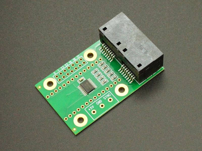
The Teensy OctoWS2811 Adapter lets the Teensy 3.2 thru Teensy 4.1 connect to thousands of WS2811, WS2812 and WS2812B addressable LEDs. When used with the OctoWS2811 library, it uses DMA (Direct Memory Access) for complex high-speed animation.
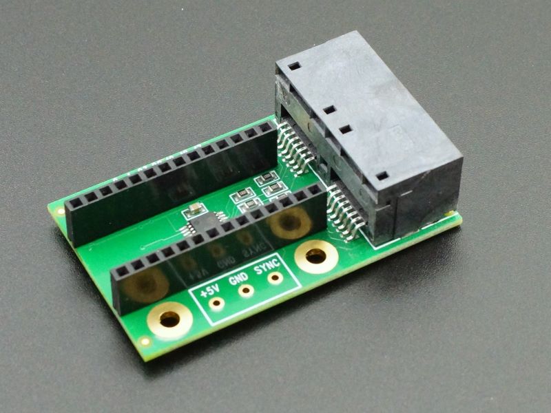
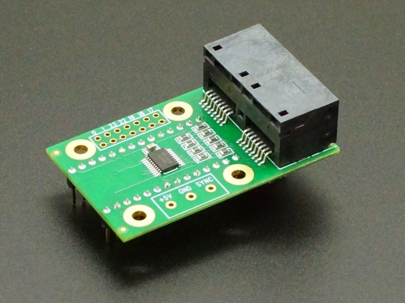
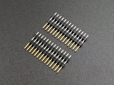
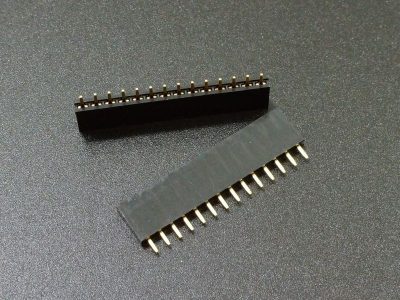
We also offer a version with female headers installed to easily mount a Teensy 4.0 or other Teensy board and another with male header pins installed to allow the adapter to plug into a solderless breadboard or female headers.
Package Includes:
- Teensy OctoWS2811 Adapter
- 4 self-threading screws
- Male header pins or female header optionally installed
KEY FEATURES OF TEENSY OCTOWS2811 Adapter:
- 8 buffered 5V outputs w/ 100 ohm series resistors
- 2 RJ45 connectors for connecting to CAT-6 cabling
- Can drive 1 to 10,000 LEDs. Maximum depends on Teensy used
- Can sync several Teensy together to drive even larger arrays.
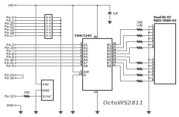
The board mounts a 74HCT245 buffer chip to provide up to 8-channels of 5V drive signals to the LED array. It uses 100 ohm series resistors to impedance match to CAT-6 cabling that is used to go from this board to the LED strips via two RJ45 connectors. This setup allows the LEDs to be remote mounted and easily disconnected from the Teensy.
The module uses pins 2, 5, 6, 7, 8, 14, 20 and 21 for driving the LEDs but the OctoWS2811 library can be configured to use only the pins you want so as not to conflict with something like the Audio Adapter if it is also being used. The File/Examples/OctoWS2811/Teensy4_PinList example in the IDE shows how to define the pins to use.
Powering the LED Strings
The addressable LEDs draw considerable power of up to 48mA each at maximum brightness. While it is possible to experiment with a small number of LEDs at lower brightness using VIN power, you should plan on running anything larger than that using an external 5V power supply of sufficient wattage to power the LEDs.
When running really large strings, the power may need to be introduced at both ends of the string or at several places within the string to minimize the voltage drop. Erratic behavior of the LEDs usually indicates an issue with insufficient power.
Mounting the OctoWS2811 Adapter
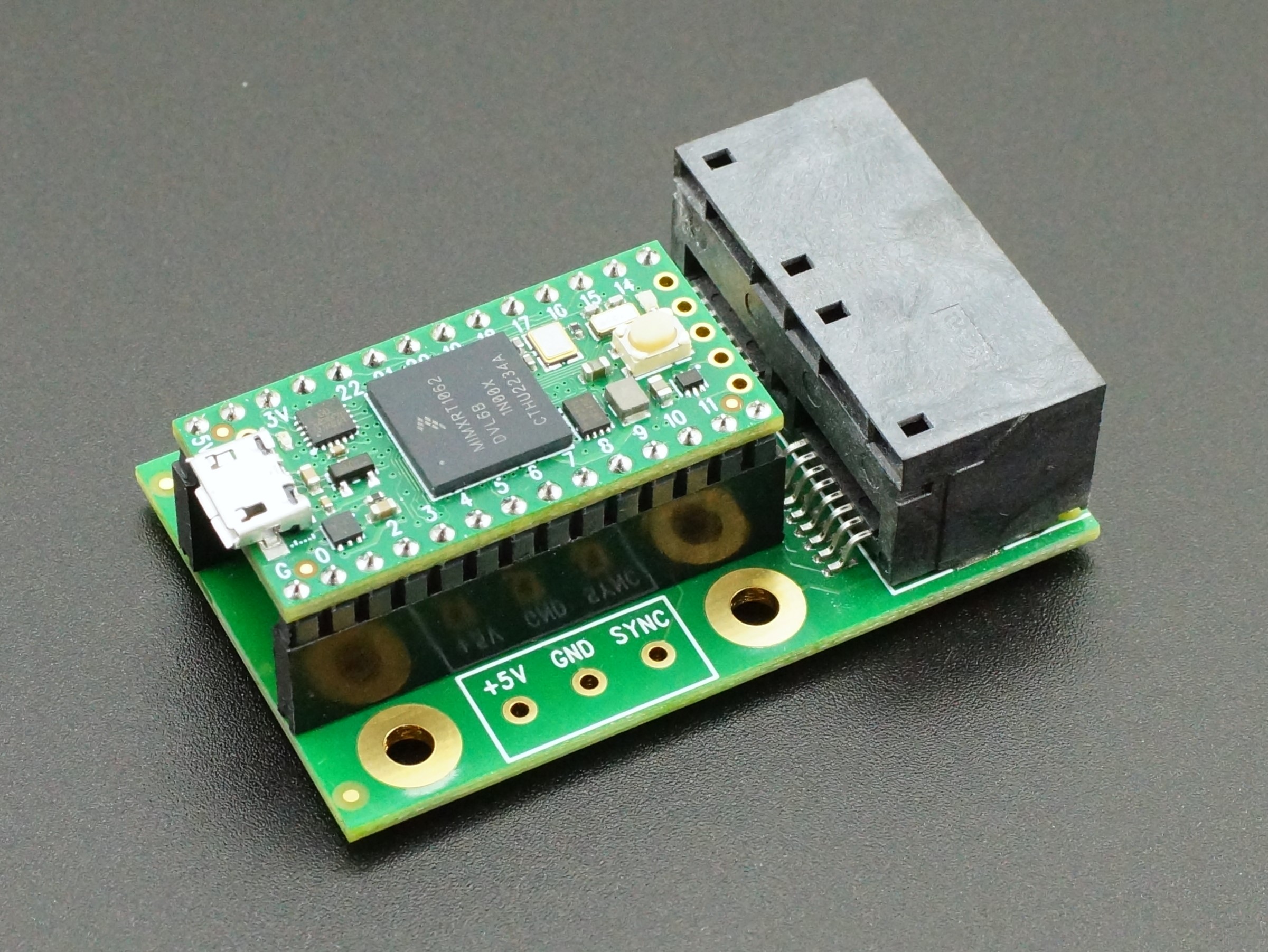
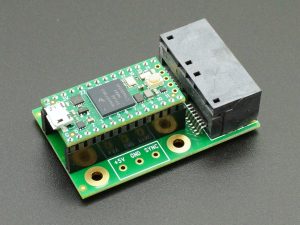
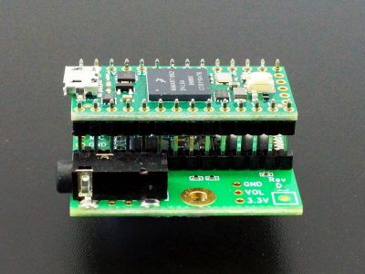
The adapter typically mounts as a shield on either the top or bottom of the Teensy board. If the adapter is mounted to the bottom of a Teensy, self-threading screws are provided to mount the board set into a plastic enclosure. The picture below shows one with the female headers installed along with a Teensy 4.0. Refer to the PJRC OctoWS2811 Adapter product page for more details on shield mounting options as well as wiring up the LEDs.
It is also possible to mount the Teensy 4.1 on the adapter by using the double-insulator headers to elevate the back of the Teensy so it clears the RJ45 connectors as shown below. The advantage of the Teensy 4.1 over the Teensy 4.0 in this application is that it includes an SD card reader and can also be loaded with additional PSRAM and Flash memory chips. We can build this version of Teensy 4.1 upon request.
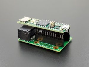
Teensy 4.1 with Double Insulator Headers
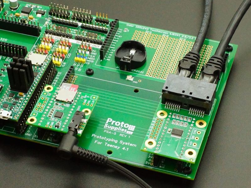
If using the adapter with the Prototyping System for Teensy 4.1, the LCD must be removed for clearance because the CAT6 cables come off the back of the module.
WS2812 Addressable LED Adapter
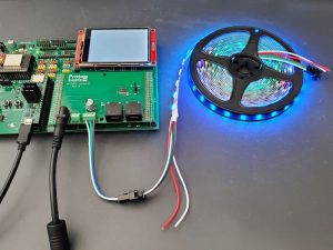
If you are working with addressable LEDs with our Prototyping System for Teensy 4.1, we now have a better option called the WS2812 Addressable LED Adapter. It includes the same functionality as the OctoWS2811 with the RJ45 connectors facing forward, but it also includes a very convenient power and data connection for a single strip of LEDs that makes it much easier to get up and running with these devices without worrying about splicing CAT6 cable.
Click on the picture for more info on this adapter.
Further Reading:
PJRC website – OctoWS2811 Product Page – More details on using this module
PJRC Blog – Many examples of using this adapter in various applications
PJRC Forum – Excellent tech support and source of information.
Notes:
- None
Technical Specifications
| I/O Logic Levels | 3.3V in, 5V output to LEDs |
| Operating Voltage | 5V |
| Maximum Operating Current | 35mA (per pin) |
| 70mA (IC package total) | |
| Board Dimensions (PCB) | 56x 34mm (2.2 x 1.35″) |
| Country of Origin | USA |
| Mfr | PJRC |
| Datasheet | 74HCT245 |

