LCD1602 16×2 Blue LCD Display
$3.49
16 character x 2 line LCD with parallel interface.
25 in stock
Description
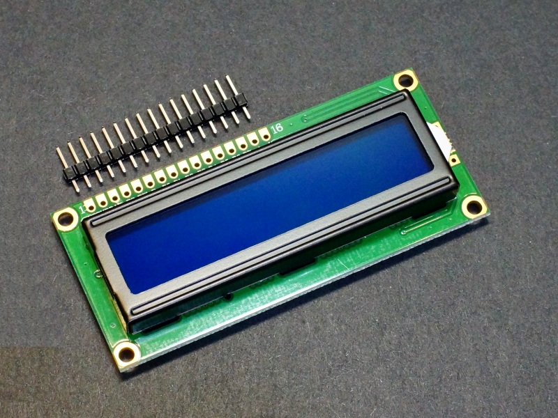
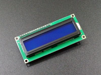
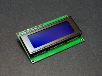
The LCD1602 16×2 Blue LCD Display provides a 16 character x 2 line LCD with parallel interface for control by an MCU.
PACKAGE INCLUDES:
- LCD1602 16×2 Blue LCD Display
- 1 x 16 Male header strip
KEY FEATURES OF LCD1602 16×2 BLUE LCD DISPLAY:
- 16 character x 2 line Blue LCD
- 4-bit and 8-bit parallel interface
- 5V operation
These displays are straightforward to use and are a great way to provide a user interface on many projects where you need more info than simple LED indicators or 7-Segment displays can provide since these are full alphanumeric displays with 2 lines of 16 characters each for a total of 32 characters. For an interactive display, pairing this type of display with a rotary encoder to navigate and select menu items on the display can provide a very nice user interface.
LCD Display
The display is composed of a 16 character x 2 line LCD display with a blue backlight and white characters. Each of the characters are composed of a 5 x 8 dot matrix for good character representation. Custom characters can be defined and used with the display.
The backlight has a VO (Display Contrast) input for connecting a potentiometer for adjustment of the contrast of the display for best viewing. The potentiometer can be somewhere in the 10K-50K range and should connect between 5V and ground. The wiper output of the potentiometer feeds the VO pin with a variable voltage that sets the contrast. If this is not adjusted correctly the display may not show any characters or solid blocks may be displayed.
The backlight is powered off the A (Anode) and K (Cathode) pins. Normally 5V is applied to ‘A’ and ground to ‘K’. The backlight includes a 51 ohm current limiting resistor, so an external resistor is not required.
The backlight can go down to about 3.2V before it goes out. It can be operated off the 3.3V line if a lower brightness is desired for the application. The backlight can be driven by a logic pin using a transistor if PWM brightness or ON/OFF control is desired
Parallel Interface
This display incorporates a parallel interface that can operate using an 8-bit (byte) mode or a 4-bit (nibble) mode. 8-bit mode uses data pins D0-D7 and 4-bit mode uses the upper data pins of D4-D7.
In practice, the 4-bit mode is normally used as it saves 4 pins on the MCU and maximizing communication speeds with the display are generally not a concern. The LiquidCrystal.h library makes the difference between using the two modes transparent to the user.
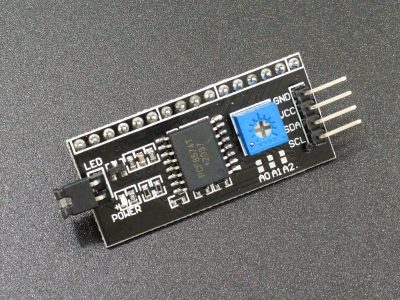
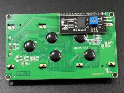
If it is desirable to minimize the pins used on the MCU even further, check out the version with an I2C interface down below which uses only 2 pins plus power and ground.
Module Connections
Connection to the display is via a 16-pin header.
1 x 16 Header
- VSS = Connect to system ground. This ground needs to be in common with the MCU
- VDD = Connect to 5V. This can come from the MCU or be a separate power supply.
- VO = Display contrast. Connect to approximately a 20K potentiometer between 5V and ground to adjust contrast of the display
- RS = Register Select. Selects the command or data register. A logic LOW = Command, HIGH = Data.
- RW = Read / Write. The display is a write only device. This pin is grounded to keep it in write mode at all times.
- E = Enable. This pin enables writing to the display when active LOW
- D0 – D7 = Data pins. D0-D7 used for 8-bit mode. D4-D7 used for 4-bit mode
- A = Backlight Anode. Connects to 5V.
- K = Backlight Cathode. Connects to ground
Assembling Module
The module ships with the male header strip loose. This allows the header to be soldered to the top or bottom of the module depending on the planned use or wires can be used to make the connections.
For breadboard use, put the headers on the bottom. Soldering is easiest if the header is first inserted into a solderless breadboard to hold it in position and keep it aligned during the soldering process.
OUR EVALUATION RESULTS:
These are good quality modules and should be in the parts bin of any hobbyist. Because of the interactivity they provide, they are both fun to play with and useful for more serious projects.
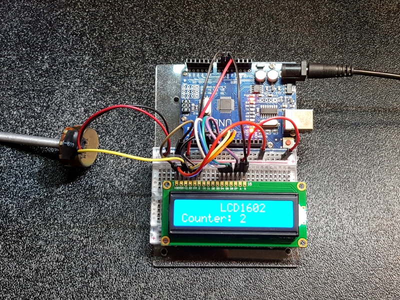
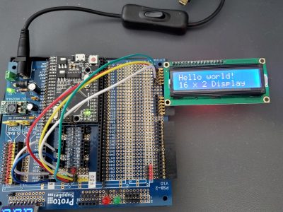
The software below uses the built-in Arduino “LiquidCrystal.h” library to show the functionality of the module.
Connections to the module are outlined in the program comments. The MCU data lines used can be changed and redefined in the following line if needed.
// Define pin connections to Arduino (RS, Enable, D4, D5, D6, D7)
LiquidCrystal lcd(8, 9, 4, 5, 6, 7);
A potentiometer is required between 5V and ground to feed the VO line to set the display contrast or else the text may not be visible. Also be sure to connect 5V and ground to the backlight A / K pins and ground the R/W pin to put the module into write mode
LCD1602 16×2 LCD Display Example Program
/*
   16x2 4-bit databus LCD Test

   Initialize the LCD and print a simple message to it.
   Then increment a counter on the 4th line every second.
   This setup uses a 4-bit bus to conserve number of MCU pins
   Connect VDD to 5V and VSS to ground on the Arduino.
   Connect RW to Ground
   Connect RS to D8, Enable to D9, D4 to D4, D5 to D5, D6 to D6, D7 to D7
   Connect A to 5V and K to Ground
   Connect a potentiometer to VO to adjust contrast of the display
*/

#include <LiquidCrystal.h>// include the library code

// Define pin connections to Arduino (RS, Enable, D4, D5, D6, D7)
LiquidCrystal lcd(8, 9, 4, 5, 6, 7);

long count = 0;
//===============================================================================
//  Initialization
//===============================================================================
void setup()
{
  lcd.begin(16, 2);  // Initialize and define the LCD's number of cols and rows:

  // Print fixed info on the display one time
  lcd.setCursor(4, 0); // set the cursor to Col 7, Line 1
  lcd.print("LCD1602");
  lcd.setCursor(0, 1);
  lcd.print("Counter: ");
}
//===============================================================================
//  Main
//===============================================================================
void loop()
{
  // Simply count up once per second until max size of 'long' type is reached,
  // then start over

  lcd.setCursor(9, 1);       // Set cursor to count location
  lcd.print(count);           // Print new count
  if (count > 100000) {   // Handle any roll-over
    count=0;
    lcd.print("          ");  // clear old count
    lcd.print(count);
  }
  count++;                    // increment count
  delay (1000);
}
BEFORE THEY ARE SHIPPED, THESE MODULES ARE:
- Sample inspected and tested per incoming shipment.
Notes:
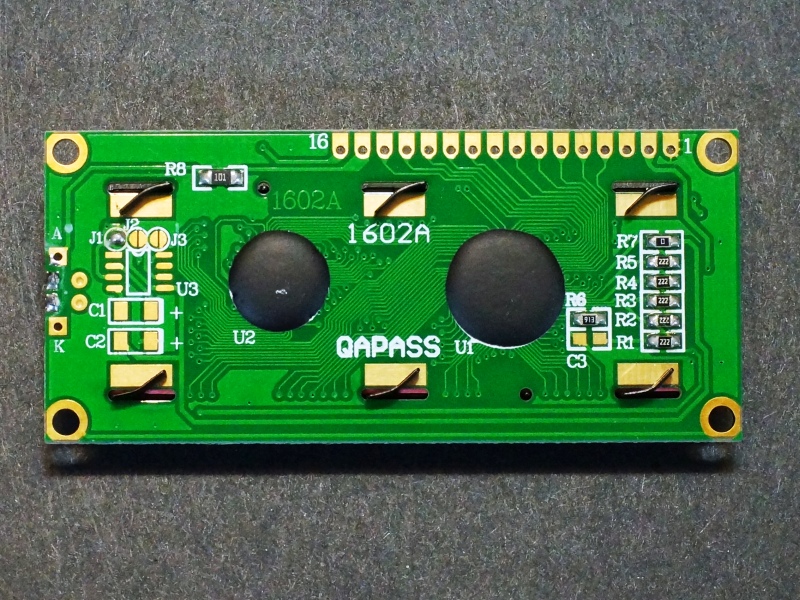
- The back of the board contains the electronics, so some care should be used to avoid possible shorting if placed on a metallic surface.
Technical Specifications
| Display | Characters | 16 characters x 2 lines |
| Backlight Color | Blue | |
| Operating Ratings | DC Power Input | 5V nominal (5.5V max) |
| Operating Current (Total) | 30mA (typical) | |
| Operating Current (Backlight Only) | 20mA (typical) | |
| Dimensions | ||
| Display Size (PCB) | 80 x 36mm (3.1″ x 1.4″) | |
| Display Height w/ PCB | 11mm (0.43″) | |
| Display Bezel | 72 x 25mm (2.8 x 1″) | |
| Country of Origin | China | |
| Datasheet | Representative example | LCD1602 Module |

