LCD I2C PCF8574 Interface Adapter
$1.79
Converts a 16×2 or 20×4 character LCD display to I2C interface
43 in stock
Description
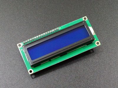
This LCD I2C interface adapter can be added to a 16 x 2 or 20 x 4 character LCD display with a standard parallel interface to make it I2C compatible. It can also be repurposed for other I2C to parallel tasks.
PACKAGE INCLUDES:
- LCD I2C Interface Adapter
KEY FEATURES OF LCD I2C INTERFACE ADAPTER:
- Provides I2C to parallel data conversion
- Backlight enable jumper
- Contrast control potentiometer
- 0x27 I2C default address. Solder jumper selectable from 0x20 – 0x27
- 100kHz I2C clock speed
- 5V operation typical, but also operates at 3.3V.
The board has a PCF8574 I2C chip that converts the I2C data from an MCU into 4-bit parallel data and control bits required by the LCD display.
By default, the industry standard HD44780 compatible 16 x 2 and 20 x 4 character LCD displays require 4 or 8 parallel data lines to drive them along with a couple of pins for chip select and chip enable. This consumes a lot of pins on the MCU. This adapter board reduces the data pin requirements to only 2 pins which can also be shared with other I2C devices.
The backlight can be controlled ON/OFF, but the intensity is not directly controllable though the I2C interface. Some modules have a jumper on the board that supplies Vcc power to the backlight. That jumper can be removed and a voltage applied to the header pin nearest the ‘LED’ markings on the board to provide power to the backlight separately. Note: Some modules do not have this header / jumper installed, instead the solder pads have a trace connecting them. It is possible to cut the trace between the pads and add header pins if desired.
The PCF8574 is a generic I2C to 8-bit I/O device and the module can be repurposed for other uses besides driving LCD modules. Max I2C clock frequency is 100kHz which makes it most suited to lower speed applications.
I2C Interface
The default I2C address is 0x27. The address is marked on the bag that the board comes in.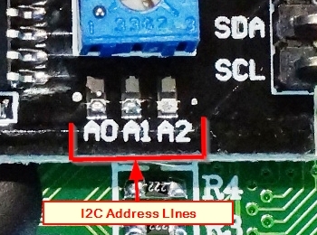
If you need to adjust the I2C address to avoid a conflict with another device, this can be done by soldering jumpers to the board.
There are 3 address jumper locations marked A0, A1, A2. Normally these lines are pulled high using built-in pull-up resistors. If you bridge these pads using a blob of solder, it grounds that address line. If you were to bridge all 3 to ground, the address would be 0x20. The range of all possible addresses spans from 0x20 to 0x27
If you are unsure of the I2C address of this or any other device, it is easy to find out what it is. Just refer to this blog post.
Module Connections
The MCU connection to the I2C adapter is via a 4 pin header.
1 x 4 Header
- GND = Connect to system ground. This ground needs to be in common with the MCU.
- VCC = Connect to 5V. This can come from the MCU or be a separate power supply. Some LCD may operate at 3.3V and this module can also operate at 3.3V
- SDA = Connect to the I2C / SDA pin on the MCU.
- SCL = Connect to the I2C / SCL pin on the MCU.
A red LED on the board lights when power is applied.
The pin-out of the header which is soldered to the LCD follows for reference, but in general you don’t need to worry about it as the I2C interface board and software library takes care of this interface unless you are adapting the module for another use. These pins are listed starting at the I2C header end of the board.
1 x 16 Header
- VSS = Ground
- VDD = Connects to VCC on the I2C header
- VO = Display contrast. Connects to the potentiometer on the module
- RS = P0 on PCF8574
- RW = P1 on PCF8574
- E = P2 on PCF8574
- D0 – D3 = Data bit 0-3 are no connects
- D4 = P4 on PCF8574
- D5 = P5 on PCF8574
- D6 = P6 on PCF8574
- D7 = P7 on PCF8574
- A = Backlight Anode. Typically connects to 5V.
- K = Backlight Cathode. Connects to ground
P3 on the PCF8574 is connected internally to the transistor on the module used to control the backlight ON/OFF.
Assembling the Adapter to the LCD
To use the adapter with an LCD, you will need to insert the 16-pin header into the 16 solder pad holes on the back of the LCD and solder them in place on the front side. The pins are long and can be cut off before or after soldering.
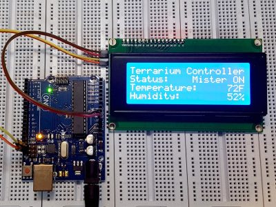
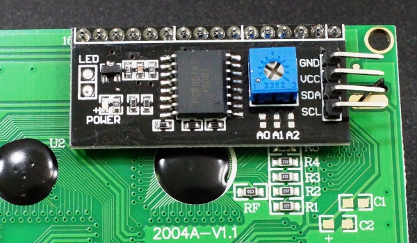
Soldering the module on is easy to do, but if you already have other pins in those holes, they will need to be removed first before this board can be added. The picture below shows the adapter mounted to the back of an LCD2004 4 x 20 character LCD.
OUR EVALUATION RESULTS:
Using the parallel interface on LCD displays is mainly interesting as a learning exercise, but for general use the I2C interface is a much better solution in almost all cases due to the large reduction in pins consumed on the MCU.
This is the same module used on our I2C compatible LCD displays we sell and is well supported using the LiquidCrystal_I2C.h and similar libraries. For using the board with software, you can check out one of the LCDs below that already have this module installed.
The PCF8574 itself is a general purpose 8-bit I/O expander for the I2C bus. The reverse engineered schematics are provided here mainly for those who may want to adapt the module to other applications. The I2C bus on this module is limited to a 100kHz clock frequency.
More info for generic applications can be found in the datasheet linked down below.
BEFORE THEY ARE SHIPPED, THESE MODULES ARE:
- Sample inspected and I2C interface verified per incoming shipment
Notes:
- None
Technical Specifications
| Operating Ratings | ||
| Vcc | range | 2.5 – 6V (5V typical) |
| Dimensions | L x W (PCB) | 42mm x 19mm (1.6 x 0.75″) |
| Country of Origin | China | |
| Datasheets | PCF8574 |