LCD2004 20×4 I2C Blue LCD Display
$7.95
20 character x 4 line LCD with I2C interface for easy control.
23 in stock
Description
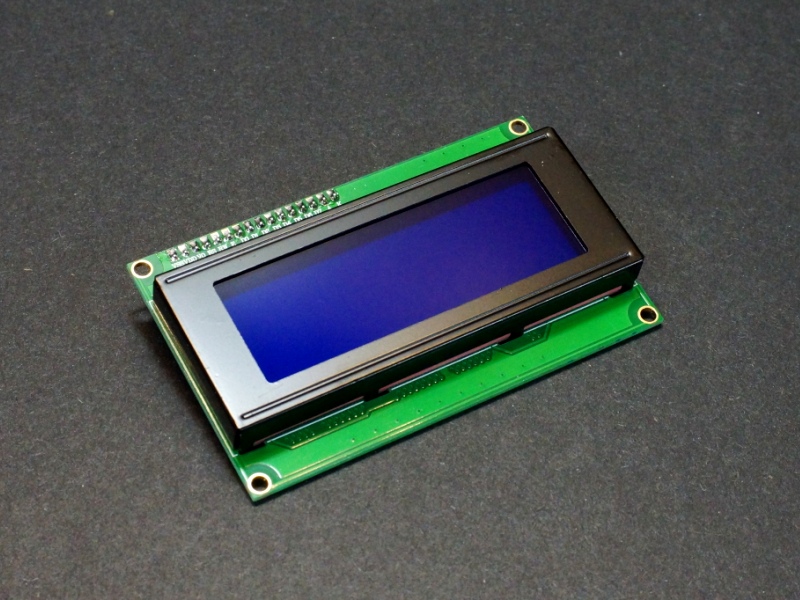
The LCD2004 20×4 I2C Blue LCD Display provides a 20 character x 4 line LCD with I2C interface for easy control by an MCU.
PACKAGE INCLUDES:
- LCD2004 20×4 I2C Blue LCD Display
KEY FEATURES OF LCD2004 20×4 I2C BLUE LCD DISPLAY:
- 20 character x 4 line Blue LCD
- I2C interface
- Adjustable backlight intensity and contrast
- 5V operation
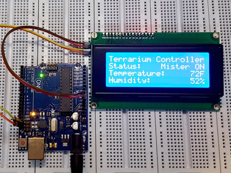
These displays are straightforward to use and are a great way to provide a user interface on many projects where you need more info than simple LED indicators or 7-Segment displays can provide since these are full alphanumeric displays with 4 lines of 20 characters each for a total of 80 characters which is a fair amount of info. For an interactive display, pairing this type of display with a rotary encoder to navigate and select menu items on the display can provide a very nice user interface.
LCD Display
The display is composed of a 20 character x 4 line LCD display with a blue backlight and white characters. Each of the characters are composed of a 5 x 8 dot matrix for good character representation.
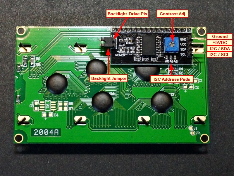
The backlight has a potentiometer for adjustment of the contrast of the display for best viewing.
The backlight intensity is not directly controllable though the I2C interface, however there is a jumper on the I2C board that supplies power to the backlight. That jumper can be removed and a voltage applied to the header pin nearest the ‘LED’ markings on the board to provide power to the backlight separately.
The backlight can go down to about 3V before it goes out. It is not known what the safe upper limit is for driving the LCD backlight so it is probably best not to exceed 5V by too much. At 5V, the backlight draws about 30mA, so it may also be possible to drive it with a PWM pin off an MCU to allow the display to be dimmed via software if desired.
I2C Interface
This display incorporates an I2C interface that requires only 2 pins on an MCU to interface with and it has good library support to get up and running fast. The I2C interface is a daughter board attached to the back of the LCD module.
The default I2C address for these displays is 0x27. The address is marked on the bag that the module comes in.
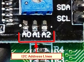
If you need to adjust I2C address to avoid a conflict, this can be done on the I2C adapter board on the back of the module. There are 3 address jumper locations marked A0, A1, A2. Normally these lines are pulled high. If you bridge these pads, it grounds that address line. If you were to bridge all 3 to ground, the address would be 0x20. The range of all possible addresses spans from 0x20 to 0x27
If you are unsure of the I2C address of this or any other device, it is easy to find out what it is. Just refer to this blog post.
Module Connections
Connection to the display is via a 4 pin header.
1 x 4 Header
- GND = Connect to system ground. This ground needs to be in common with the MCU.
- VCC = Connect to 5V. This can come from the MCU or be a separate power supply.
- SDA = Connect to the I2C / SDA pin on the MCU.
- SCL = Connect to the I2C / SCL pin on the MCU.
A red LED on the I2C interface board lights when power is applied.
OUR EVALUATION RESULTS:
These are good quality modules and should be in the parts bin of any hobbyist. Because of the interactivity they provide, they are both fun to play with and useful for more serious projects.
You will find the raw 20×4 displays without the I2C interface being sold and we sell them ourselves. Those have a parallel bus interface that requires many pins on the microcontroller to control, so it is generally best to stick with the I2C interface version like this one unless you specifically want or need to work with the parallel interface.
The software below uses the Arduino “LiquidCrystal_I2C.h” library to test the functionality of the module.
Note that the I2C address of the module we sell is 0x27 (39 decimal) but can be adjusted if needed as explained above. The address will be printed on the label on the bag.
LCD2004 20×4 I2C LCD Display Example Program
/*
 * 20x4 LCD Test
 *
 * Initialize the LCD, then print a simple message to it
 * Connect SCL to A5, SDA to A4 (on UNO) or to the dedicated SCL and SDA pins,
 * Connect Vcc to 5V and GND to ground on the Arduino.
 * Need to install library LiquidCrystal_I2C.
 */

#include <Wire.h>
#include <LiquidCrystal_I2C.h>

LiquidCrystal_I2C lcd(0x27,20,4);  // set the LCD address to 0x27 for a 20 chars and 4 line display

//===============================================================================
//  Initialization
//===============================================================================
void setup() {

  lcd.begin();
  lcd.clear();
  lcd.backlight();      // Make sure backlight is on

  // Print a message onb both lines of the LCD.
  lcd.setCursor(0,0);   //Set cursor to character 0 on line 0
  lcd.print("Hello World");
  lcd.setCursor(0,1);   //Move cursor to character 0 on line 1
  lcd.print("Line 2");
  lcd.setCursor(7,2);   //Move cursor to character 6 on line 2
  lcd.print("Line 3");
  lcd.setCursor(14,3);   //Move cursor to character 15 on line 3
  lcd.print("Line 4");
}
//===============================================================================
//  Main
//===============================================================================
void loop() {

}
BEFORE THEY ARE SHIPPED, THESE MODULES ARE:
- Sample inspected and tested per incoming shipment.
Notes:
- The back of the board contains the electronics, so some care should be used to avoid possible shorting if placed on a metallic surface.
Technical Specifications
| Display | Characters | 20 characters x 4 lines |
| Backlight Color | Blue | |
| Operating Ratings | DC Power Input | 5V |
| Operating Current (Total) | 40mA (typical) | |
| Operating Current (Backlight Only) | 30mA (typical) | |
| Dimensions | ||
| Display Size (PCB) | 99 x 60mm (3.9″ x 2.36″) | |
| Display Height w/ PCB | 21mm (0.83″) | |
| Display Bezel | 97 x 40mm (3.82 x 1.58″) | |
| Country of Origin | China |


