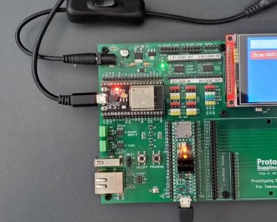
Powering Up The System
One of the scariest things about working with the Teensy boards is knowing that if you accidentally apply power through the USB connector and the VIN 5V pin at the same time, bad things can happen.
That is easy to do if you have a setup that uses VIN power and then decide to connect the USB to download new code. This effectively shorts the 5V USB power coming from the computer or hub to the DC power coming from some external power supply which can potentially result in damage to the computer, hub, external power supply or Teensy.
Fortunately, the Prototyping System for Teensy 4.1 baseboard has features that manage the various input power sources to ensure they all get along without having to think about what is plugged in or powered up.
It is safe to plug in USB to the Teensy 4.1, the ESP32-S and also apply DC power using an external AC/DC power supply in any combination at the same time.
DC Input Power
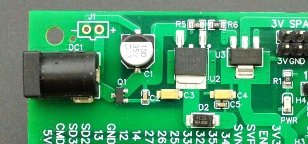
The baseboard can be powered from 6.5 – 9VDC via a standard DC power jack.
The baseboard uses linear regulators to minimize electrical noise and while the input can technically be fed with higher voltages up to 30VDC, the linear regulators drop the excess voltage via heat, so it is always best to keep the input voltage down toward the lower end to minimize power dissipation in the regulators. This is especially true if you plan to draw much power from the baseboard. Our 7.5V AC adapter works well with this setup. A 6.5V power source is ideal.
Besides the standard DC power jack, there is also a footprint J1 for an optional 0.1″ 2-pin screw terminal or JST style connector for bringing in power or for powering an external device off the DC input such as a fan.
Reverse voltage protection on the DC input section is provided by a MOSFET transistor Q1.
The output of the 5V regulator U2 has a series Schottky diode D2 to prevent current flow back towards the regulator if another power source is connected to the baseboard.
Teensy USB Input Power
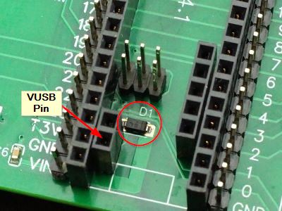
Besides the standard DC jack input, the baseboard can also be powered from USB on the Teensy 4.1 or the ESP32-S.
The Teensy socket has a diode D1 . This is used to prevent current flow from VIN power to the USB connector power pin (VUSB). Current can only flow from VUSB to VIN. This diode on the baseboard allows the user to use their own Teensy if they have one without having to try to solder a diode to the bottom of the Teensy which can be difficult. They just need to cut the VUSB/VIN trace and solder in the VUSB header pin as detailed down below.
If using something to pry the Teensy 4.1 up to remove it from the socket, use care not to dislodge this diode. The good news is if you ordered our modified Teensy 4.1 as noted below, there is a second diode in parallel so this diode is redundant and technically not needed.
ProtoSupplies.com Modified Teensy 4.1
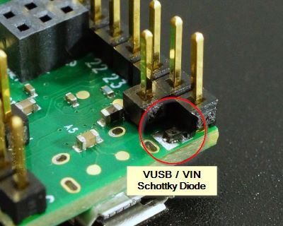
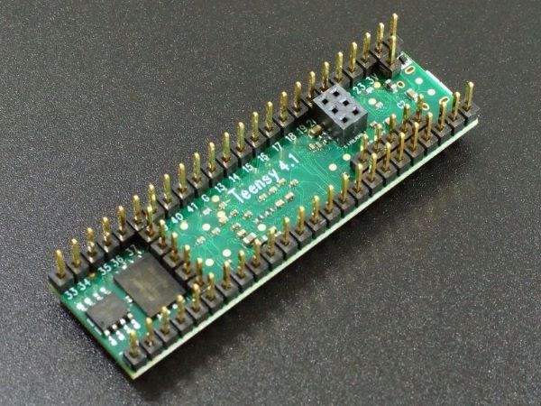
If you order one of the Teensy 4.1 that we configure for this system Teensy 4.1 Fully Loaded For Prototyping System, they have the USB and VIN power isolated by cutting the VUSB / VIN trace.
In addition, a 1A Schottky diode is installed on the bottom of the Teensy as shown here. This serves the same purpose as the diode on the Prototyping System board and is in parallel with it so it is redundant.
This diode allows the Teensy 4.1 to be powered off the USB cable without having to plug it into a baseboard to complete the power circuit which can be useful at times. It also allows it to be used in custom baseboards designed by customers without having to worry about doing the diode modification.
These Teensy 4.1s have the female ethernet connector and the Host USB and VBAT 5-pin headers installed on the bottom side to mate with I/O connectors on the baseboard. They are also available with various memory configurations. An 8MB PSRAM and 256MB / 2G-bit NAND Flash are installed in the example shown below.
Modifying Your Own Teensy 4.1 For Use With Prototyping System
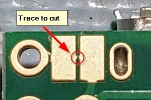
If you happen to have a Teensy 4.1 laying around and want to modify it for use with this baseboard, you just need to cut the VUSB / Vin trace and solder on the VUSB header pin and the diode on the baseboard is put into the circuit.
The trace to cut is very small and located between the two large solder pads under the USB connector. A magnifier helps when cutting this trace.
Use a sharp X-Acto or box knife and press down at about a 45 to 60 degree angle on one end of the trace to cut through the copper trace near one pad. Rotate the angle of the knife and repeat on the other end of the trace near the other pad to remove a small wedge of trace. Since the copper is soft, you shouldn’t need to ‘saw’ through the trace which can leave slivers of copper that can re-short the trace.
If you have an ohmmeter, it is a good idea to measure across the two pads after making the cut to ensure they are no longer have a complete short.
To solder the VUSB header on the Teensy, insert the pin into the female header on the baseboard as shown below. You can also add the 5-pin Host USB and VBAT male headers at the same time if you want to use those features. If you don’t already have a male header soldered into the Ethernet header location on the Teensy, you can add a female ethernet header at the same to the top of the extended male header on the baseboard.
If you already have a male Ethernet header installed on the Teensy, do not try to unsolder it or you will almost certainly damage the Teensy. You can instead use an IDC cable like comes in the Ethernet kit to connect the male header on the Teensy to the male header next to the RJ45 Ethernet jack on the baseboard.
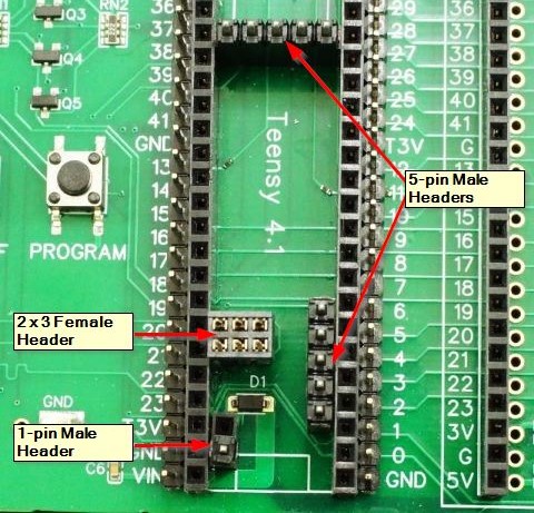
Once the headers are in place, install the Teensy into the socket making sure the pins of the headers you just installed all line up with the holes in the Teensy and protrude through. Then solder all pins in place.
ESP32-S USB Input Power
The optional ESP32-S module includes a Schottky diode between the USB and VIN power already on the module.
Similar to the Teensy, it prevents current flow from its main power pin back into its USB connector.
Theory of Operation
All of these Schottky diodes allow current to flow from any of the different power sources into the baseboard to power the system. More importantly, they prevent any current from flowing in the reverse direction and back into those power sources.
When current flows through a Schottky diode there is about a 0.3V voltage drop. The actual voltage drop will vary a bit depending on how much current is flowing through the diode.
The DC power jack input uses an adjustable LM317 regulator with its output set for 5.4V using resistors R5 and R6. This means the VIN power after the diode is about 5.4V – 0.3V = 5.1V. The 5V USB power from the Teensy 4.1 or ESP32-S are in the 5V – 0.3V = 4.7V range. These voltages are shown in the power control portion of the schematic below.
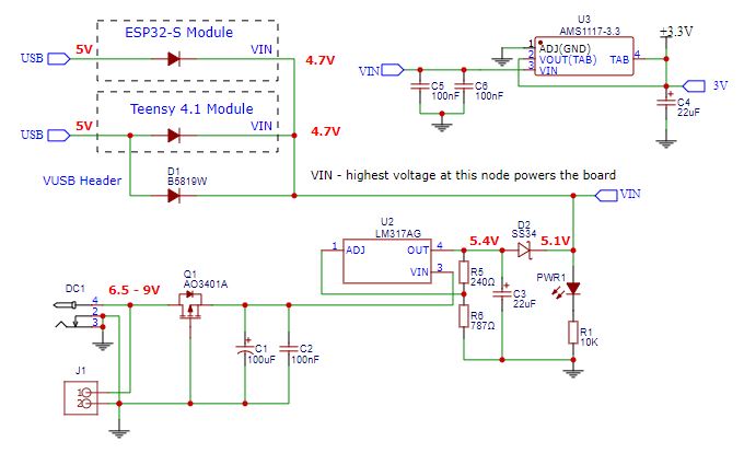
If multiple power sources are connected, the source with the highest voltage will take priority as the diodes on the other power sources will be reverse biased. This voltage is labeled as VIN or 5V on the baseboard in various places.
The reason for setting the LM317 to 5.4V is that this arrangement helps ensure that if both the DC jack power and USB power are connected, the DC jack will have the higher voltage and be used to power the baseboard rather than drawing from the USB. It also ensures the 5V rail has a valid 5V since 4.7V is a little below the minimum of 4.75 specified by most 5V logic.
This 4.7V – 5.1V VIN power provides power to the Teensy 5V VIN input, the ESP32-S 5V input and the LCD display Vcc input which all have their own built-in 3.3V regulators.
This VIN power is also connected to the 5V logic side of level shifters and 5V pins like in the proto adapter area. If a full 5V is needed for finicky 5V logic, just ensure that the DC jack has power.
3.3V Power
The baseboard also has its own 3.3V regulator powered from the VIN power rail which provides 3.3V power to circuits that require it. It is labeled 3V on the board.
The Teensy 3.3V regulator is not used to power any external circuits to minimize the load on the Teensy. It also helps to protect the Teensy as accidentally shorting its 3.3V output is one of the most common ways that they are damaged. That Teensy 3.3V is available on two pins labeled T3V on the Teensy socket. If it is used, be sure not to connect the T3V to the main 3V or ground on the baseboard or damage to the Teensy can occur.
The ESP32-S also has a 3.3V output labeled 3V3 on its socket and it is also unused on the board but available for use if desired with the same caveat to not connect it to 3V or ground.
