Example Software
If the Fully Stuffed prototyping system is ordered along with a Teensy 4.1, the system comes preconfigured with some example software preloaded in both the Teensy 4.1 and ESP32-S.
This software is intended to verify basic configuration and operation of the system and provide a bit of instant gratification upon receiving the system by just applying power. For those that are just getting started with learning how to program, it provides a simple framework that can easily be modified to learn about working with some of the core features of the system.
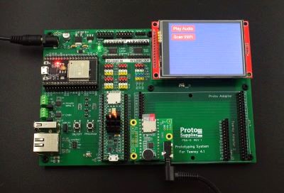
To get started, simply plug the earbuds or headphones into the Audio Adapter and apply power. If you started with your own Teensy 4.1 or ESP32-S, you will need to download the software to them that can be found near the bottom of this page.
The programs are not overly clever on the programming to make them easier to follow and modify. They pull heavily from various sample programs. The communications between the Teensy 4.1 and ESP32-S in particular are handled in a very simplistic fashion by passing simple text strings without any error checking.
There are two programs. One is for the Teensy 4.1 and the second is for the ESP32-S if one is installed. The Teensy 4.1 program was updated in June 2023 to also print system configuration information to the LCD as well as send it out the serial port.
Teensy 4.1 Program Overview
- Initializes the LCD and serial ports.
- Checks to see if any of the optional PSRAM or Flash memory chips have been installed and reports that info out the USB serial port and also prints it to the LCD screen. If you ordered a system with the Teensy 4.1 already installed, this also provides a way to easily verify that you received the correct version without having to pry the Teensy 4.1 out of its socket to look at the chips.
- Paints a couple of buttons on the display. One for playing audio and one for scanning for WiFi networks.
- Implements a simple serial communication path with the ESP32-S to see if one is attached. First asking if one is out there by sending a ‘?’ and looking for a ‘Y’ yes in return. If found, it enables the Scan button.
- If Scan is pressed, it sends the command ‘S’ for scan to the ESP32-S and then looks for a response back with the found networks. The found networks are then listed on the display.
- It also looks for an Audio Adapter with an SD card installed with the SDTEST2.WAV file on it (can be found at https://www.pjrc.com/teensy/td_libs_AudioDataFiles.html.) If found, it enables the Play Audio button to allow the audio to be started and stopped. These files are included on the SD card with the Fully Stuffed version.
- It reports various things such as the touch coordinates and touch screen button hits out to the USB port for display in a Serial Monitor window if one is open.
ESP32-S Program Overview
- Looks for incoming serial commands from the Teensy.
- If it gets a command ‘?’, it responds with ‘Y’ to let the Teensy 4.1 know that yes, I am here.
- If it gets a command ‘S’, it scans for networks and reports the results back to the Teensy 4.1
- It also reports the scan information out the USB port for display in a Serial Monitor window if one is open.
- This program is based largely on the WiFiScan example program.
Using 2 Arduino IDE Windows For Multitasking
If the ESP32-S is installed and you have two USB cables like come with the Fully Stuffed version, you can open two instances of the IDE with one connected to the Teensy 4.1 and one connected to the ESP32-S. This permits downloading programs to both processors and the Serial Monitor windows can be open simultaneously on both processors to monitor what is going on.
This makes it easy to make program changes like changing button color to see the effect or creating new commands for communicating between the two microcontrollers and downloading new code to either processor without messing with moving cables or changing the IDE settings.
To open two separate instances of the IDE, they both need to be launched by clicking on the application icon. You should then be able to see two IDE icons in the task bar.
Teensy 4.1 Program Details
We’ll first take a look at each of the functional sections of the Teensy 4.1 program with the complete program listings at the bottom of the page.
Initialize Serial Ports for USB and ESP32-S Communications
The first thing the Teensy 4.1 program does is initialize the USB port for serial mode of operation at 115200 baud for display in the Serial Monitor window.
The Serial 1 port of the Teensy 4.1 is hardwired to the Serial 2 port of the ESP32-S. It initializes Serial1 for communication with the ESP32-S at 115,200 baud. The baud rate is arbitrary and just needs to match the baud rate that the ESP32-S serial port is set to.
#define ESP32SERIAL Serial1 // ESP32-S is attached to Serial1 port
Serial.begin(115200); // Initialize USB serial port for Serial Monitor window
begin(115200);        // Initialize ESP32-S serial port
Initialize the TFT LCD Display
Next it initializes the TFT LCD.
It uses the ILI9341_T3.h library for LCD control and it loads Arial fonts font_Arial.h for drawing characters on the LCD screen.
The LCD uses Teensy 4.1 pin 40 for chip select and pin 9 for DC (Data / Command). The DC pin determines if the data going to the LCD is Data for it to display or a Command to execute. These pins are hardwired on the baseboard.
The LCD can display in all 4 orientations, so tft.setRotation(3) is used to rotate the image to fit the orientation it has on the baseboard.
#include <ILI9341_t3.h>
#include <font_Arial.h>
// LCD control pins defined by board
#define TFT_CS 40
#define TFT_DC  9

// Use main SPI bus MOSI=11, MISO=12, SCK=13 with different control pins
ILI9341_t3 tft = ILI9341_t3(TFT_CS, TFT_DC);
// Setup LCD screen
tft.begin();
tft.setRotation(3);
Useful Tip – SPI Bus Initialization
One key thing to keep in mind when rolling your own software is that the LCD, Touchscreen and the Audio Adapter SD card all sit on the same SPI bus. When working with this system with these installed, you need to initialize them with separate chip selects so that they do not conflict with each other even if you aren’t actively using them.
The basic code above can be used to initialize the LCD.
If you don’t need some modules for what you are working on, such as the LCD or Audio Adapter for instance, it can also simply be unplugged from the system when you are not using it if you don’t want to bother initializing it.
Initialize the Touchscreen
Next it initializes the touchscreen overlay of the LCD.
It uses the library XPT2046_Touchscreen.h which is the touch controller used on the LCD.
The touchscreen chip select is on Teensy pin 41. The optional IRQ output of the touchscreen is on Teensy pin 2. This interrupt is not used in the example. These pins are hardwired on the baseboard. The IRQ on pin 2 can be disabled by removing the jumper labeled 2-T_IRQ by the LCD if you want to use the Teensy pin 2 for something else.
The touchscreen offsets relates to the coordinates reported by the touchscreen when it is touched in the 4 corners. Default values can be used, but these can be adjusted to best match the physical touch of the screen to the expected coordinates.
The touchscreen also has a rotation parameter, so ts.setRotation(1) is used to rotate the touch overlay to fit the orientation it has on the baseboard. Note that the orientation of the LCD and touchscreen are different as the touchscreen is inverted relatively to the LCD.
When the program is running, the Serial Monitor window will display the coordinates of any touches. If you touch the top left corner, it should report something close to 400, 400. Similarly the bottom right should report something close to 3879, 3843. If it doesn’t, these numbers can be adjusted to help calibrate the touch coordinates to the display coordinates. If these coordinates are too far off, you may have to press next to the button rather than on it to active the button.
#include <XPT2046_Touchscreen.h>
// touchscreen offset for four corners
#define TS_MINX 400
#define TS_MINY 400
#define TS_MAXX 3879
#define TS_MAXY 3843
// Touch screen control pins defined by board
// TIRQ interrupt if used is on pin 2
#define TS_CS  41
//#define TIRQ_PIN  2
XPT2046_Touchscreen ts(TS_CS);  // Param 2 = NULL - No interrupts
  // Setup touch Screen
  ts.begin();
  ts.setRotation(1);
Find any PSRAM or Flash that may be installed
The next thing the Teensy 4.1 program does is to look to see if any external PSRAM or Flash is installed and reports what it finds out to the Serial Monitor window and also displays it on the LCD.
PSRAM uses external_psram_size which is a built-in function that returns the size of any PSRAM that may be installed. This will either be 0, 8 or 16 for Megabytes.
For flash memory, it uses the LittleFS.h library which provides access to the Flash memory.
Since the Flash memory comes in both NOR and NAND technologies depending on the memory capacity, it looks for both to see if it can find either and if not, it reports no Flash installed.
#include "LittleFS.h"
uint8_t external_psram_size;
  // Check for PSRAM chip installed
  uint8_t size = external_psram_size;
  Serial.printf("PSRAM Memory Size = %d Mbyte\n", size);
  tft.printf("PSRAM Memory Size = %d Mbyte\n", size);
  if (size == 0) {
    Serial.println ("No PSRAM Installed");
    tft.println ("No PSRAM Installed");
  }
  tft.println();

  LittleFS_QSPIFlash myfs_NOR;    // NOR FLASH
  LittleFS_QPINAND myfs_NAND;      // NAND FLASH 1Gb

  // Check for NOR Flash chip installed
  if (myfs_NOR.begin()) {
    Serial.printf("NOR Flash Memory Size = %d Mbyte / ", myfs_NOR.totalSize() / 1048576);
    Serial.printf("%d Mbit\n", myfs_NOR.totalSize() / 131072);
    tft.printf("NOR Flash Memory Size = %d Mbyte / ", myfs_NOR.totalSize() / 1048576);
    tft.printf("%d Mbit\n", myfs_NOR.totalSize() / 131072);
  }
  // Check for NAND Flash chip installed
  else if (myfs_NAND.begin()) {
    Serial.printf("NAND Flash Memory Size =  %d bytes / ", myfs_NAND.totalSize());
    Serial.printf("%d Mbyte / ", myfs_NAND.totalSize() / 1048576);
    Serial.printf("%d Gbit\n", myfs_NAND.totalSize() * 8 / 1000000000);
    tft.println("NAND Flash Memory Size = ");
    tft.printf("%d bytes / ", myfs_NAND.totalSize());
    tft.printf("%d Mbyte / ", myfs_NAND.totalSize() / 1048576);
    tft.printf("%d Gbit\n", myfs_NAND.totalSize() * 8 / 1000000000);
  }
  else {
    Serial.printf("No Flash Installed\n");
    tft.printf("No Flash Installed\n");
  }
  tft.println();
Check if Audio Adapter with SD card is installed
Next it looks to see if the Audio Adapter with SD card in installed by trying to initialize the SD card. If the Audio Adapter is not installed or it is installed, but does not have an SD card in it, the initialization will fail.
The audioAdapterAttached flag is set true if the adapter is found.
  // Check for Audio bd with SD card installed
  if (!(SD.begin(SDCARD_CS_PIN))) {
    Serial.println("Audio board with SD card not found");
    tft.println("Audio board with SD card not found");
    audioAdapterAttached = false;
  }
  else {
    Serial.println("Audio board with SD card is attached");
    tft.println("Audio board with SD card is attached");
    audioAdapterAttached = true;
  }
  tft.println();
Check if ESP32-S WiFi Processor is installed
Next it looks to see if the ESP32-S in installed by trying to communicate with it over the serial port. This example software uses a very simple communication mechanism between the two microcontrollers by passing text strings over the serial port. In this case, the Teensy 4.1 sends the character ‘?’ to the ESP32-S to query if it is attached.
It then checks to see if it gets a response. If the response is the character ‘Y’, it knows the ESP32 is attached and sets the esp32Attached flag true, otherwise it assumes it is not attached.
  // Check for ESP32 installed
  ESP32SERIAL.print("?");   // Ask ESP32 if it is there
  delay (100);              // Wait a bit for ESP32 to respond
  if (ESP32SERIAL.available()) {  // If there is a response
    String returnData = ESP32SERIAL.readString();
    if (returnData == 'Y') {  // ESP32S responded with Y for Yes, I'm here
      esp32SAttached = true;
      Serial.println("ESP32S was found");
      tft.println("ESP32S was found");
    }
    else {      // No response or invalid response
      Serial.println("ESP32S not found");
      tft.println("ESP32S not found");
      esp32SAttached = false;
    }
  }
Draw Some Buttons
The program then draws a couple of buttons on the display.
The display is 320 pixels horizontal x 240 pixels vertical. The defines set the coordinates of the buttons relative to the screen pixels. It sets the upper x/y pixel of the button and then the width and height of the button in pixels.
The BUTTON_FONT Arial_14 sets the size and type of font to use on the button. In this case it is Arial font, 14pt in size.
The Audio button acts as a toggle which turns playback of the Audio file SDTEST2.WAV on or off.
The Scan button sends a scan request to the ESP32-S by sending an ‘S’ to it.
Two subroutines SetAudioButton() and SetScanButton() are used to draw the buttons and also control their action when pressed. A boolean value is passed to these subroutines; TRUE means the button is active. The Audio button plays the .WAV file, the Scan button initiates a scan and the button text and color is updated to an active state. FALSE means the button is inactive. The Audio button stops playing the .WAV file and both update the button text and color to an inactive state.
// Define Audio button location and size
#define AUDIO_X 10
#define AUDIO_Y 10
#define AUDIO_W 105
#define AUDIO_H 32

// Define Scan button location and size
#define SCAN_X 10
#define SCAN_Y 50
#define SCAN_W 105
#define SCAN_H 32
#define BUTTON_FONT Arial_14
  //Draw buttons
  SetAudioButton (false);
  SetScanButton (false);
//===============================================================================
//  Routine to draw Audio button current state and control audio playback
//===============================================================================
void SetAudioButton (boolean audio)
{
  tft.setCursor(AUDIO_X + 8, AUDIO_Y + 8);
  tft.setFont(BUTTON_FONT);
  tft.setTextColor(ILI9341_WHITE);

  if (!audio) {  // button is set inactive, redraw button inactive
    tft.fillRoundRect(AUDIO_X, AUDIO_Y, AUDIO_W, AUDIO_H, 4, ILI9341_RED);
    tft.print ("Play Audio");
    audioPlaying = false;
    if (playSdWav1.isPlaying()) { // Stop any audio that is playing
      playSdWav1.stop();
      Serial.println ("Audio being stopped");
    }
  }
  else {          // button is active, redraw button active
    tft.fillRoundRect(AUDIO_X, AUDIO_Y, AUDIO_W, AUDIO_H, 4, ILI9341_GREEN);
    tft.print ("Playing");
    audioPlaying = true;
    if (audioAdapterAttached && !playSdWav1.isPlaying()) { // Play audio file
      Serial.println("Audio being played");
      playSdWav1.play("SDTEST2.WAV");
      delay(10); // wait for library to parse WAV info
    }
  }
}
//===============================================================================
//  Routine to draw scan button current state and initiate scan request
//===============================================================================
void SetScanButton (boolean scanning)
{
  tft.setCursor(SCAN_X + 8, SCAN_Y + 8);
  tft.setFont(BUTTON_FONT);
  tft.setTextColor(ILI9341_WHITE);

  if (!scanning) {  // Button is inactive, redraw button
    tft.fillRoundRect(SCAN_X, SCAN_Y, SCAN_W, SCAN_H, 4, ILI9341_RED);
    tft.print ("Scan WiFi");
  }
  else {          // Button is active, redraw button
    tft.fillRect(1, SCAN_Y + SCAN_H, 360, 240, ILI9341_BLUE); // Clear previous scan
    tft.fillRoundRect(SCAN_X, SCAN_Y, SCAN_W, SCAN_H, 4, ILI9341_GREEN);
    tft.print ("Scanning");
    ESP32SERIAL.println("S");   // Send command to ESP32 to start scan
    scanRequested = true;       // Set flag that we requested scan
    Serial.println ("Scan being requested");
  }
}
Setup the Audio Adapter and the Audio Adapter SD Card
If the Audio Adapter and the SD card was found, it sets it up for use.
It uses the SPI.h, Audio.h, Wire.h, SD.h and SerialFlash.h libraries
The Audio Adapter is configured in the section starting with AudioPlaySdWav playSdWav1; These configuration settings and required libraries are automatically generated by the Audio System Design Tool. We will explore that tool later in the Audio Workshop Tutorial.
The SD card on the Audio Adapter sits on the main SPI bus. Its chip select is on the Teensy 4.1 pin 10, MOSI on pin 11 and SCK on pin 13. These are hardwired by the baseboard.
Note that the SCK pin 13 is shared with the on-board LED of the Teensy. This means the LED will light during SCK activity. It also means that if you intentionally set the pin, such as to turn the LED on, the SCK will no longer function.
If it cannot find the SD card, it greys out the Audio button.
#include <SPI.h>
#include <Audio.h>
#include <Wire.h>
#include <SD.h>
#include <SerialFlash.h>
AudioPlaySdWav           playSdWav1;
AudioOutputI2S           i2s1;
AudioConnection          patchCord1(playSdWav1, 0, i2s1, 0);
AudioConnection          patchCord2(playSdWav1, 1, i2s1, 1);
AudioControlSGTL5000     sgtl5000_1;
// Pins used with the Teensy Audio Shield
#define SDCARD_CS_PIN    10
#define SDCARD_MOSI_PIN  11 //7
#define SDCARD_SCK_PIN   13 //14
  // Setup audio
  if (audioAdapterAttached) { // Setup the audio
    AudioMemory(8);
    sgtl5000_1.enable();
    sgtl5000_1.volume(0.5);
    SPI.setMOSI(SDCARD_MOSI_PIN);
    SPI.setSCK(SDCARD_SCK_PIN);
  }
  else {  // If no audio, gray out button
    tft.setCursor(AUDIO_X + 8, AUDIO_Y + 8);
    tft.setFont(BUTTON_FONT);
    tft.setTextColor(ILI9341_WHITE);
    tft.fillRoundRect(AUDIO_X, AUDIO_Y, AUDIO_W, AUDIO_H, 4, ILI9341_DARKGREY);
    tft.print ("No Audio");
  }
Setup the ESP-32
Technically, there is nothing to actually setup, so it just checks the flag to see if the ESP32 is installed and if it is not, it greys out the button and sets the test to ‘No Scan”.
  // Setup ESP32
  if (!esp32SAttached) { // If no ESP32 gray out button
    tft.setCursor(SCAN_X + 8, SCAN_Y + 8);
    tft.setFont(BUTTON_FONT);
    tft.setTextColor(ILI9341_WHITE);
    tft.fillRoundRect(SCAN_X, SCAN_Y, SCAN_W, SCAN_H, 4, ILI9341_DARKGREY);
    tft.print ("No Scan");
  }
Main Loop
The main loop of the program does a few things.
First it checks to see if audio was previously playing and is now finished. If so, it updates the Audio button.
Next it checks to see if the touchscreen has been touched. If there is a new touch:
- It maps the touch coordinates to the screen pixel coordinates.
- It checks to see if if one of the buttons was touched based on their coordinates.
- If the Scan button was touched, it calls the SetScanButton (TRUE) which sends a scan request ‘S’ to the ESP32-S. It then looks for the return scan data from the ESP32-S and displays it on the LCD.
- If the Audio button was touched, it toggles between playing or stopping the SDTEST2.WAV file by calling the SetPlayButton with TRUE or FALSE.
- It sends the touch coordinates to the USB for display in the Serial Monitor window.
//===============================================================================
//  Main
//===============================================================================
void loop() {
  // Keep an eye on any audio that may be playing and reset button when it ends
  if (playSdWav1.isStopped() && audioPlaying) { // Audio finished playing
    SetAudioButton(false);
    Serial.println("Audio finished playing");
  }
  // Check to see if the touch screen has been touched
  if (ts.touched() && isTouched == false) {
    TS_Point p = ts.getPoint();
    // Map the touch point to the LCD screen
    p.x = map(p.x, TS_MINY, TS_MAXY, 0, tft.width());
    p.y = map(p.y, TS_MINX, TS_MAXX, 0, tft.height());
    isTouched = true;

    // Look for a Scan Button Hit
    if ((p.x > SCAN_X) && (p.x < (SCAN_X + SCAN_W))) {
      if ((p.y > SCAN_Y) && (p.y <= (SCAN_Y + SCAN_H))) {
        Serial.println("Scan Button Hit");
        if (esp32SAttached) SetScanButton (true);
      }
    }
    // Look for an Audio Button Hit
    if ((p.x > AUDIO_X) && (p.x < (AUDIO_X + AUDIO_W))) {
      if ((p.y > AUDIO_Y) && (p.y <= (AUDIO_Y + AUDIO_H))) {
        Serial.println("Audio Button Hit");
        if (audioAdapterAttached && !audioPlaying) {
          SetAudioButton(true);
        }
        else if (audioAdapterAttached && audioPlaying) {
          SetAudioButton(false);
        }
      }
    }
    Serial.print("x = ");   // Show our touch coordinates for each touch
    Serial.print(p.x);
    Serial.print(", y = ");
    Serial.print(p.y);
    Serial.println();
    delay(100);           // Debounce touchscreen a bit
  }
  if (!ts.touched() && isTouched) {
    isTouched = false;  // touchscreen is no longer being touched, reset flag
  }
  // If we requested a scan, look for serial data coming back from the ESP32S
  if (scanRequested && ESP32SERIAL.available()) {
    Serial.print("Read incoming data");
    tft.setCursor(10, 90);
    tft.setFont(Arial_10);
    while (ESP32SERIAL.available()) { // Print the scan data to the LCD & USB
      String returnData = ESP32SERIAL.readString();
      tft.println (returnData);
      Serial.println(returnData);
    }
    scanRequested = false;  // Reset the scan flag and button
    SetScanButton (false);
  }
}
Below is the fully Teensy 4.1 program which can be copied and downloaded into the Teensy 4.1 if needed.
Full Teensy 4.1 Program
/*
  Teensy 4.1 Prototyping System Board Example

  This program checks for presence of PSRAM/Flash memory the Audio adapter
  with SD card and the ESP32.  Send the results to the LCD and serial port and
  then draws 2 buttons on the LCD screen - Audio and Scan

  If Audio adapter is attached with an SD card installed, the Audio
  button plays the wave file "SDTEST2.WAV" from the Teensy audio tutorial
  https://www.pjrc.com/teensy/td_libs_AudioDataFiles.html

  The Scan button sends a command to the ESP32S requesting a scan of
  available WiFi networks.  When the ESP32S returns the scan results,
  the Teensy 4.1 updates those results on the LCD screen and serial port.
  This requires an ESP32S to be installed and the sample program
  ESP32_Teensy_41_Demo be loaded on it, which is just a modified version
  of the ESP32 WiFiScan example program.

  This example code is in the public domain.
*/
#include <ILI9341_t3.h>
#include <font_Arial.h>
#include <XPT2046_Touchscreen.h>
#include <SPI.h>
#include <Audio.h>
#include <Wire.h>
#include <SD.h>
#include <SerialFlash.h>
#include "LittleFS.h"
extern "C" uint8_t external_psram_size;

AudioPlaySdWav           playSdWav1;
AudioOutputI2S           i2s1;
AudioConnection          patchCord1(playSdWav1, 0, i2s1, 0);
AudioConnection          patchCord2(playSdWav1, 1, i2s1, 1);
AudioControlSGTL5000     sgtl5000_1;

// Pins used with the Teensy Audio Shield
#define SDCARD_CS_PIN    10
#define SDCARD_MOSI_PIN  11 //7
#define SDCARD_SCK_PIN   13 //14

// touchscreen offset for four corners
#define TS_MINX 400
#define TS_MINY 400
#define TS_MAXX 3879
#define TS_MAXY 3843

// LCD control pins defined by the baseboard
#define TFT_CS 40
#define TFT_DC  9

// Use main SPI bus MOSI=11, MISO=12, SCK=13 with different control pins
ILI9341_t3 tft = ILI9341_t3(TFT_CS, TFT_DC);

// Touch screen control pins defined by the baseboard
// TIRQ interrupt if used is on pin 2
#define TS_CS  41
//#define TIRQ_PIN  2
XPT2046_Touchscreen ts(TS_CS);  // Param 2 = NULL - No interrupts

// Define Audio button location and size
#define AUDIO_X 10
#define AUDIO_Y 10
#define AUDIO_W 105
#define AUDIO_H 32

// Define Scan button location and size
#define SCAN_X 10
#define SCAN_Y 50
#define SCAN_W 105
#define SCAN_H 32
#define BUTTON_FONT Arial_14

#define ESP32SERIAL Serial1  // ESP32 is attached to Serial1 port

// Subroutine prototypes
void SetScanButton (boolean);   // Handles Scan button when touched
void SetAudioButton (boolean);  // Handles Audio button when touched

// Misc flags to keep track of things
boolean isTouched = false;      // Flag if a touch is in process
boolean scanRequested = false;  // Flag if WiFi scan is in process
boolean audioAdapterAttached = false; // Flag if audio bd with SD card attached
boolean audioPlaying = false;  // Flag if audio is currently playing
boolean esp32SAttached = false;  // Flag if ESP32S is attached

//===============================================================================
//  Initialization
//===============================================================================
void setup() {
  Serial.begin(115200);       //Initialize USB serial port to computer
  ESP32SERIAL.begin(115200);  //Initialize Seria1 1 connected to ESP32S

  // Setup LCD screen
  tft.begin();
  tft.setRotation(3);  // Rotates screen to match the baseboard orientation
  // Setup touch Screen
  ts.begin();
  ts.setRotation(1);  // Sets the touch screen orientation
  tft.fillScreen(ILI9341_BLUE);
  tft.setCursor(1, 110);  // Set initial cursor position
  tft.setFont(Arial_10);  // Set initial font style and size

  // Check for PSRAM chip installed
  uint8_t size = external_psram_size;
  Serial.printf("PSRAM Memory Size = %d Mbyte\n", size);
  tft.printf("PSRAM Memory Size = %d Mbyte\n", size);
  if (size == 0) {
    Serial.println ("No PSRAM Installed");
    tft.println ("No PSRAM Installed");
  }
  tft.println();

  LittleFS_QSPIFlash myfs_NOR;    // NOR FLASH
  LittleFS_QPINAND myfs_NAND;      // NAND FLASH 1Gb

  // Check for NOR Flash chip installed
  if (myfs_NOR.begin()) {
    Serial.printf("NOR Flash Memory Size = %d Mbyte / ", myfs_NOR.totalSize() / 1048576);
    Serial.printf("%d Mbit\n", myfs_NOR.totalSize() / 131072);
    tft.printf("NOR Flash Memory Size = %d Mbyte / ", myfs_NOR.totalSize() / 1048576);
    tft.printf("%d Mbit\n", myfs_NOR.totalSize() / 131072);
  }
  // Check for NAND Flash chip installed
  else if (myfs_NAND.begin()) {
    Serial.printf("NAND Flash Memory Size =  %d bytes / ", myfs_NAND.totalSize());
    Serial.printf("%d Mbyte / ", myfs_NAND.totalSize() / 1048576);
    Serial.printf("%d Gbit\n", myfs_NAND.totalSize() * 8 / 1000000000);
    tft.println("NAND Flash Memory Size = ");
    tft.printf("%d bytes / ", myfs_NAND.totalSize());
    tft.printf("%d Mbyte / ", myfs_NAND.totalSize() / 1048576);
    tft.printf("%d Gbit\n", myfs_NAND.totalSize() * 8 / 1000000000);
  }
  else {
    Serial.printf("No Flash Installed\n");
    tft.printf("No Flash Installed\n");
  }
  tft.println();

  // Check for Audio bd with SD card installed
  if (!(SD.begin(SDCARD_CS_PIN))) {
    Serial.println("Audio board with SD card not found");
    tft.println("Audio board with SD card not found");
    audioAdapterAttached = false;
  }
  else {
    Serial.println("Audio board with SD card is attached");
    tft.println("Audio board with SD card is attached");
    audioAdapterAttached = true;
  }
  tft.println();

  // Check for ESP32 installed
  ESP32SERIAL.print("?");   // Ask ESP32 if it is there
  delay (100);              // Wait a bit for ESP32 to respond
  if (ESP32SERIAL.available()) {  // If there is a response
    String returnData = ESP32SERIAL.readString();
    if (returnData == 'Y') {  // ESP32S responded with Y for Yes, I'm here
      esp32SAttached = true;
      Serial.println("ESP32S was found");
      tft.println("ESP32S was found");
    }
    else {      // No response or invalid response
      Serial.println("ESP32S not found");
      tft.println("ESP32S not found");
      esp32SAttached = false;
    }
  }

  // Draw buttons
  SetAudioButton (false);
  SetScanButton (false);

  // Setup audio
  if (audioAdapterAttached) { // Setup the audio
    AudioMemory(8);
    sgtl5000_1.enable();
    sgtl5000_1.volume(0.5);
    SPI.setMOSI(SDCARD_MOSI_PIN);
    SPI.setSCK(SDCARD_SCK_PIN);
  }
  else {  // If no audio, gray out button
    tft.setCursor(AUDIO_X + 8, AUDIO_Y + 8);
    tft.setFont(BUTTON_FONT);
    tft.setTextColor(ILI9341_WHITE);
    tft.fillRoundRect(AUDIO_X, AUDIO_Y, AUDIO_W, AUDIO_H, 4, ILI9341_DARKGREY);
    tft.print ("No Audio");
  }

  // Setup ESP32
  if (!esp32SAttached) { // If no ESP32 gray out button
    tft.setCursor(SCAN_X + 8, SCAN_Y + 8);
    tft.setFont(BUTTON_FONT);
    tft.setTextColor(ILI9341_WHITE);
    tft.fillRoundRect(SCAN_X, SCAN_Y, SCAN_W, SCAN_H, 4, ILI9341_DARKGREY);
    tft.print ("No Scan");
  }
}
//===============================================================================
//  Main
//===============================================================================
void loop() {
  // Keep an eye on any audio that may be playing and reset button when it ends
  if (playSdWav1.isStopped() && audioPlaying) { // Audio finished playing
    SetAudioButton(false);
    Serial.println("Audio finished playing");
  }
  // Check to see if the touch screen has been touched
  if (ts.touched() && isTouched == false) {
    TS_Point p = ts.getPoint();
    // Map the touch point to the LCD screen
    p.x = map(p.x, TS_MINY, TS_MAXY, 0, tft.width());
    p.y = map(p.y, TS_MINX, TS_MAXX, 0, tft.height());
    isTouched = true;

    // Look for a Scan Button Hit
    if ((p.x > SCAN_X) && (p.x < (SCAN_X + SCAN_W))) {
      if ((p.y > SCAN_Y) && (p.y <= (SCAN_Y + SCAN_H))) {
        Serial.println("Scan Button Hit");
        if (esp32SAttached) SetScanButton (true);
      }
    }
    // Look for an Audio Button Hit
    if ((p.x > AUDIO_X) && (p.x < (AUDIO_X + AUDIO_W))) {
      if ((p.y > AUDIO_Y) && (p.y <= (AUDIO_Y + AUDIO_H))) {
        Serial.println("Audio Button Hit");
        if (audioAdapterAttached && !audioPlaying) {
          SetAudioButton(true);
        }
        else if (audioAdapterAttached && audioPlaying) {
          SetAudioButton(false);
        }
      }
    }
    Serial.print("x = ");   // Show our touch coordinates for each touch
    Serial.print(p.x);
    Serial.print(", y = ");
    Serial.print(p.y);
    Serial.println();
    delay(100);           // Debounce touchscreen a bit
  }
  if (!ts.touched() && isTouched) {
    isTouched = false;  // touchscreen is no longer being touched, reset flag
  }
  // If we requested a scan, look for serial data coming back from the ESP32S
  if (scanRequested && ESP32SERIAL.available()) {
    Serial.print("Read incoming data");
    tft.setCursor(10, 90);
    tft.setFont(Arial_10);
    while (ESP32SERIAL.available()) { // Print the scan data to the LCD & USB
      String returnData = ESP32SERIAL.readString();
      tft.println (returnData);
      Serial.println(returnData);
    }
    scanRequested = false;  // Reset the scan flag and button
    SetScanButton (false);
  }
}
//===============================================================================
//  Routine to draw Audio button current state and control audio playback
//===============================================================================
void SetAudioButton (boolean audio)
{
  tft.setCursor(AUDIO_X + 8, AUDIO_Y + 8);
  tft.setFont(BUTTON_FONT);
  tft.setTextColor(ILI9341_WHITE);

  if (!audio) {  // button is set inactive, redraw button inactive
    tft.fillRoundRect(AUDIO_X, AUDIO_Y, AUDIO_W, AUDIO_H, 4, ILI9341_RED);
    tft.print ("Play Audio");
    audioPlaying = false;
    if (playSdWav1.isPlaying()) { // Stop any audio that is playing
      playSdWav1.stop();
      Serial.println ("Audio being stopped");
    }
  }
  else {          // button is active, redraw button active
    tft.fillRoundRect(AUDIO_X, AUDIO_Y, AUDIO_W, AUDIO_H, 4, ILI9341_GREEN);
    tft.print ("Playing");
    audioPlaying = true;
    if (audioAdapterAttached && !playSdWav1.isPlaying()) { // Play audio file
      Serial.println("Audio being played");
      playSdWav1.play("SDTEST2.WAV");
      delay(10); // wait for library to parse WAV info
    }
  }
}
//===============================================================================
//  Routine to draw scan button current state and initiate scan request
//===============================================================================
void SetScanButton (boolean scanning)
{
  tft.setCursor(SCAN_X + 8, SCAN_Y + 8);
  tft.setFont(BUTTON_FONT);
  tft.setTextColor(ILI9341_WHITE);

  if (!scanning) {  // Button is inactive, redraw button
    tft.fillRoundRect(SCAN_X, SCAN_Y, SCAN_W, SCAN_H, 4, ILI9341_RED);
    tft.print ("Scan WiFi");
  }
  else {          // Button is active, redraw button
    tft.fillRect(1, SCAN_Y + SCAN_H, 360, 240, ILI9341_BLUE); // Clear previous scan
    tft.fillRoundRect(SCAN_X, SCAN_Y, SCAN_W, SCAN_H, 4, ILI9341_GREEN);
    tft.print ("Scanning");
    ESP32SERIAL.println("S");   // Send command to ESP32 to start scan
    scanRequested = true;       // Set flag that we requested scan
    Serial.println ("Scan being requested");
  }
}
ESP32-S Program Details
The ESP32-S program is simply the WiFiScan example program that has been modified slightly to interact with the Teensy 4.1 through its Serial 2 port.
It looks for the ‘?’ and ‘S’ characters on the Serial 2 port. If it receives a ‘?’, it responds with a ‘Y’ to let the Teensy 4.1 know that it is present. If it receives an ‘S’, it initiates a scan. Once a scan is completed, the data it sends to the USB port for display in the Serial Monitor window is also now mirrored to the Serial 2 port for use by the Teensy 4.1.
Below is the fully ESP32-S program which can be copied and downloaded into the ESP32-S if needed.
Full ESP32-S Program
/*
    This sketch interfaces to the Teensy 4.1 via serial port 2.
    It demonstrates how to receive a request for a scan for WiFi networks and
    report the results back via serial port.

    This is a simple variation of the ESP32 WiFiScan example program
*/
#include "WiFi.h"

#define RX2 16  // Teensy 4.1 is connected to serial port #2
#define TX2 17

const int LED_PIN = 2;  // We will light the LED when Scan is in process.
//===============================================================================
//  Initialization
//===============================================================================
void setup()
{
  Serial.begin(115200);   // USB port
  Serial2.begin(115200, SERIAL_8N1, RX2, TX2);  //Port connected to Teensy 4.1

  // Set WiFi to station mode and disconnect from an AP if previously connected
  WiFi.mode(WIFI_STA);
  WiFi.disconnect();
  delay(100);
  pinMode(LED_PIN, OUTPUT);
  Serial.println("Setup done");
}
//===============================================================================
//  Main
//===============================================================================
void loop()
{
  if (Serial2.available()) {
    char command = Serial2.read();
    Serial.println(command);
    if (command == '?') { // Are you there?
      Serial.println("Y");
      Serial2.print("Y");  // Acknowledge I'm attached
    }
    if (command == 'S'){
      Serial.println("scan start");
      digitalWrite(LED_PIN, HIGH);   // turn the LED on
      // WiFi.scanNetworks will return the number of networks found
      int n = WiFi.scanNetworks();
      Serial.println("scan done");
      if (n == 0) {
        Serial.println("no networks found");
        Serial2.println("No networks found");
      } else {
        Serial.print(n);
        Serial2.print(n);
        Serial.println(" Networks Found");
        Serial2.println(" Networks Found");
        for (int i = 0; i < n; ++i) {
          // Print SSID and RSSI for each network found to both USB and
          // out Serial2 to attached Teensy 4.1
          Serial.print(i + 1);
          Serial2.print(i + 1);
          Serial.print(": ");
          Serial2.print(": ");
          Serial.print(WiFi.SSID(i));
          Serial2.print(WiFi.SSID(i));
          Serial.print(" (");
          Serial2.print(" (");
          Serial.print(WiFi.RSSI(i));
          Serial2.print(WiFi.RSSI(i));
          Serial.print(")");
          Serial2.print(")");
          Serial.println((WiFi.encryptionType(i) == WIFI_AUTH_OPEN) ? " " : "*");
          Serial2.println((WiFi.encryptionType(i) == WIFI_AUTH_OPEN) ? " " : "*");
        }
       }
      }
  digitalWrite(LED_PIN, LOW);    // turn the LED off
  }
}