Audio Workshop 15
Data Visualization – Peak Detection
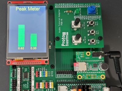
In this last part of the original workshop series, we will use our built-in display for visualization of the peak detect analysis.
This not only provides a little visual gratification after staring at FFT data in the last tutorial, but also shows a couple of new techniques for using the LCD such as using the LCD in portrait orientation.
Fortunately, unlike the original workshop, all the messy LCD wiring is already done for us so we can get straight to designing the system.
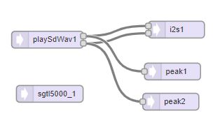
Design the Audio System
We are going to use the same audio system that we used in Workshop 13 for detecting peak audio levels.
Draw the audio system below.
Turn the Design into Code and Use it in a Program
Compared to the original Part_3_03_TFT_Display we are initializing the LCD with our pins and also initializing the touch since it also sits on the SPI bus in our system.
Note that one thing that is different from previous examples is that we are not setting the LCD rotation. The default rotation puts the LCD into the portrait display as we are using here.
To draw the bars a simple but effective method is used to draw the green bar rectangle at the new height based on the peak data and then draw the remaining bar above in black to match the background color and make it disappear.
Copy and paste the code below into the IDE window.
// Advanced Microcontroller-based Audio Workshop
//
// http://www.pjrc.com/store/audio_tutorial_kit.html
// https://hackaday.io/project/8292-microcontroller-audio-workshop-had-supercon-2015
//
// Part 3-3: Add a TFT Display
// ProtoSupplies.com Changes and Additions
//    Initialize the LCD using the baseboard pinout
#include <ILI9341_t3.h>
#include <font_Arial.h> // from ILI9341_t3
#include <XPT2046_Touchscreen.h>


///////////////////////////////////
// copy the Design Tool code here
///////////////////////////////////


// LCD control pins defined by baseboard
#define TFT_CS 40
#define TFT_DC  9

// Use main SPI bus MOSI=11, MISO=12, SCK=13 with different control pins
ILI9341_t3 tft = ILI9341_t3(TFT_CS, TFT_DC);

// Touch screen control pins defined by baseboard
// TIRQ interrupt if used is on pin 2
#define TS_CS  41
//#define TIRQ_PIN  2
XPT2046_Touchscreen ts(TS_CS);  // Param 2 = NULL - No interrupts

// Use these with the Teensy Audio Adapter
#define SDCARD_CS_PIN    10
#define SDCARD_MOSI_PIN  7
#define SDCARD_SCK_PIN   14

// Use these with the Teensy 4.1 SD card
//#define SDCARD_CS_PIN    BUILTIN_SDCARD
//#define SDCARD_MOSI_PIN  11  // not actually used
//#define SDCARD_SCK_PIN   13  // not actually used

//===============================================================================
//  Initialization
//===============================================================================
void setup() {
  Serial.begin(9600);
  delay(500);
  tft.begin();
  ts.begin();
  tft.fillScreen(ILI9341_BLACK);
  tft.setTextColor(ILI9341_YELLOW);
  tft.setFont(Arial_24);
  //tft.setTextSize(3);
  tft.setCursor(40, 8);
  tft.println("Peak Meter");

  AudioMemory(10);
  sgtl5000_1.enable();
  sgtl5000_1.volume(0.5);
  SPI.setMOSI(SDCARD_MOSI_PIN);
  SPI.setSCK(SDCARD_SCK_PIN);
  if (!(SD.begin(SDCARD_CS_PIN))) {
    while (1) {
      Serial.println("Unable to access the SD card");
      delay(500);
    }
  }
  delay(1000);
}

elapsedMillis msecs;
//===============================================================================
//  Main
//==============================================================================
void loop() {
  if (playSdWav1.isPlaying() == false) {
    Serial.println("Start playing");
    //playSdWav1.play("SDTEST1.WAV");
    //playSdWav1.play("SDTEST2.WAV");
    playSdWav1.play("SDTEST3.WAV");
    //playSdWav1.play("SDTEST4.WAV");
    delay(10); // wait for library to parse WAV info
  }

  if (msecs > 15) {  // Update display every 15 milliseconds
    if (peak1.available() && peak2.available()) {
      msecs = 0;
      float leftNumber = peak1.read();
      float rightNumber = peak2.read();
      Serial.print(leftNumber);
      Serial.print(", ");
      Serial.print(rightNumber);
      Serial.println();

      // draw the verticle bars
      int height = leftNumber * 240;
      tft.fillRect(60, 280 - height, 40, height, ILI9341_GREEN);
      tft.fillRect(60, 280 - 240, 40, 240 - height, ILI9341_BLACK);
      height = rightNumber * 240;
      tft.fillRect(140, 280 - height, 40, height, ILI9341_GREEN);
      tft.fillRect(140, 280 - 240, 40, 240 - height, ILI9341_BLACK);
      // a smarter approach would redraw only the changed portion...

      // draw numbers underneath each bar
      tft.setFont(Arial_14);
      tft.fillRect(60, 284, 40, 16, ILI9341_BLACK);
      tft.setCursor(60, 284);
      tft.print(leftNumber);
      tft.fillRect(140, 284, 40, 16, ILI9341_BLACK);
      tft.setCursor(140, 284);
      tft.print(rightNumber);
    }
  }
}
Now Export and copy and paste the Design Tool code into the program to complete it, then verify and upload the program to the Teensy.
When the Teensy begins running the program, you should see the display show a simple visualization of the peak level meter for both the left and right channels as the WAV file plays.