Audio Workshop 1
Audio Tutorial Adapter and Testing of the Audio Hardware
Audio Tutorial Adapter

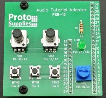
To facilitate going through the tutorials, we have created the Audio Tutorial Adapter. This adapter provides the user interface buttons and potentiometers as used on the original PJRC breadboard setup with a few modifications.
The buttons have been moved from pins 0-2 to pins 3-5 on the Teensy to avoid conflicts with the baseboard.
The two main potentiometers are still on A2 and A3
It also includes a third potentiometer connected to pin 15 (A1) that can be used for volume control rather than using the harder to find and use potentiometer that fits on the Audio Adapter.
There is an LED on pin 24 that can be used instead of the on-board LED connected to pin 13. This is to avoid conflict with the Audio Adapter SD card that uses the same pin for SCK.
While it was designed for the audio tutorials, the adapter can also be used to provide general purpose buttons, potentiometers and an LED for other experiments such as working with the PT8211 module.
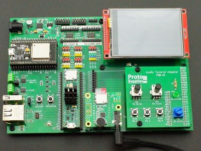
The Audio Tutorial Adapter is designed to fit in the right side of the proto adapter area while the Teensy Audio Adapter sits on the left side. Nylon standoffs are provided to support the adapter.
In addition to the Audio Tutorial Adapter, to complete the audio tutorials you will need the Prototyping System baseboard, Teensy 4.1, LCD, Audio Adapter 4.x (Rev D) with microphone, SD card with WAV files loaded and headphones. These are all included with the Fully Stuffed version of the baseboard. Audio Adapters shipping on the Fully Stuffed version as of July ’22 have the microphone installed.

Hardware Test
The program below does a basic check of the audio hardware to make sure your setup is ready to go.
Install the two standoffs in the Audio Tutorial Adapter for physical support and then install the adapter into the right side of the adapter area. The threaded end of the standoffs go through the baseboard. Nuts are provided, but do not need to be installed.
If an Teensy 4.x Audio Adapter is not already installed, plug one into the left side of the adapter area and then plug the headphones into the audio jack.
We won’t go into details of the program because those will be covered in later tutorials.
Copy and paste the program below into a new window on the Arduino IDE and then compile and download it to the Teensy 4.1. You will need to verify that the board type is set to Teensy 4.1 under Tools/Board and that it sees the Teensy under Tools/Port.
Once the program is downloaded it will send constant beeps to the headphone and blink the LED on the Audio Tutorial Adapter each time it beeps.
Open the Serial Monitor window to see the effects of pushing the buttons or twiddling the knobs.
The pushbuttons will report both the press and release of each of the three buttons (3-5).
The potentiometers will each report a number between 0-1023 as they are being turned. They won’t reach the extreme high or low values, so don’t be surprised if they may read something like 25-1005.
It will also report each time a beep is sent to headphones.
// Advanced Microcontroller-based Audio Workshop
//
// Part 1-2: Test Hardware
//
// Sends beep to headset
// Reports button and potentiometer settings
//
// ProtoSupplies.com Changes and Additions:
//    Change pin #s to match tutorial adapter to avoid conflicts
//    Add LED blink for new LED

#include <Audio.h>
#include <Wire.h>
#include <SD.h>
#include <SPI.h>
#include <SerialFlash.h>
#include <Bounce.h>

AudioSynthWaveform    waveform1;
AudioOutputI2S        i2s1;
AudioConnection       patchCord1(waveform1, 0, i2s1, 0);
AudioConnection       patchCord2(waveform1, 0, i2s1, 1);
AudioControlSGTL5000  sgtl5000_1;

Bounce button0 = Bounce(3, 15);
Bounce button1 = Bounce(4, 15);
Bounce button2 = Bounce(5, 15);

const int LED = 24;

int count=1;
int a1history=0, a2history=0, a3history=0;
//===============================================================================
//  Initialization
//===============================================================================
void setup() {
  AudioMemory(10);
  pinMode(3, INPUT_PULLUP);
  pinMode(4, INPUT_PULLUP);
  pinMode(5, INPUT_PULLUP);
  pinMode(24, OUTPUT);
  Serial.begin(115200);
  sgtl5000_1.enable();
  sgtl5000_1.volume(0.3);
  waveform1.begin(WAVEFORM_SINE);
  delay(1000);
  button0.update();
  button1.update();
  button2.update();
  a1history = analogRead(A1);
  a2history = analogRead(A2);
  a3history = analogRead(A3);
}
//===============================================================================
//  Main
//===============================================================================
void loop() {
  digitalWrite (LED, HIGH);
  Serial.print("Beep #");
  Serial.println(count);
  count = count + 1;
  waveform1.frequency(440);
  waveform1.amplitude(0.9);
  wait(250);
  digitalWrite (LED, LOW);
  waveform1.amplitude(0);
  wait(1750);
}
//===============================================================================
//  Wait Subroutine
//===============================================================================
void wait(unsigned int milliseconds)
{
  elapsedMillis msec=0;

  while (msec <= milliseconds) {
    button0.update();
    button1.update();
    button2.update();
    if (button0.fallingEdge()) Serial.println("Button (pin 3) Press");
    if (button1.fallingEdge()) Serial.println("Button (pin 4) Press");
    if (button2.fallingEdge()) Serial.println("Button (pin 5) Press");
    if (button0.risingEdge()) Serial.println("Button (pin 3) Release");
    if (button1.risingEdge()) Serial.println("Button (pin 4) Release");
    if (button2.risingEdge()) Serial.println("Button (pin 5) Release");
    int a1 = analogRead(A1);
    int a2 = analogRead(A2);
    int a3 = analogRead(A3);
    if (a1 > a1history + 10 || a1 < a1history - 10) {
      Serial.print("Knob (pin A1) = ");
      Serial.println(a1);
      a1history = a1;
    }
    if (a2 > a2history + 10 || a2 < a2history - 10) {
      Serial.print("Knob (pin A2) = ");
      Serial.println(a2);
      a2history = a2;
    }
    if (a3 > a3history + 10 || a3 < a3history - 10) {
      Serial.print("Knob (pin A3) = ");
      Serial.println(a3);
      a3history = a3;
    }
  }
}
