Pay Additional Charges
Recent Blog Entries
-

Teensy 4.1 and Teensy 4.0 Low Profile Options: New Lows in Custom PCB Design
We often get customer requests for providing lo... -
Project System for Teensy 4.1 Now Available
We have just introduced our new Project System ...


Teensy 4.1 Fully Loaded For Prototyping System (Low Profile)
$43.95 – $59.95
Low profile bottom mounted I/O for most PCB baseboards.
Select Configuration
Description
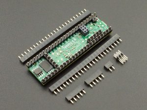
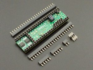
For the vertically challenged, the Teensy 4.1 Fully Loaded for Prototyping System (Low Profile) is like our standard Fully Loaded for Prototyping System product, but built with very short low profile male headers and shipped with the mating low profile female header sockets and a male Ethernet header for mounting on a baseboard. It includes the same memory options as our standard Teensy 4.1 Fully Loaded product along with additional changes for it to work properly in PCB baseboards that bring the Teensy 4.1 I/O out from the bottom of the board.
If you are looking for a Teensy 4.1 fully loaded with memory that will work with solderless breadboards, head to this link: https://protosupplies.com/product/teensy-4-1-fully-loaded/
If you are looking for a Teensy 4.1 fully loaded with memory and low profile headers but don’t need the bottom mounted I/O, head over to this link: https://protosupplies.com/product/teensy-41-fully-loaded-low-profile/
Please Note: Since this item is hand-modified, we can configure and ship additional assemblies within one or two business days if we have the base Teensy 4.1 and chips in stock. If you have requirements for a larger number than we show in stock or need further customization such as being built using the Lockable version of Teensy 4.1 or want some headers not installed, email us at support@protosupplies.com with your requirements.
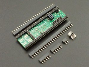
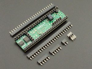
Package Includes:
- Teensy 4.1 configured as outlined below and based on selected memory option.
- Qty 2 – 1×24 mating low profile female header sockets
- Qty 2 – 1×5 mating low profile female header sockets (for USB Host and VBAT, PROG and ON/OFF)
- Qty 1 – 1×2 mating low profile female header socket (for VUSB)
- Qty 1 – 2×3 2mm male Ethernet header (for mating with female Ethernet header installed on bottom side of Teensy)
- Handy pinout diagram
The following changes are made to the base Teensy 4.1 product:
- The VUSB/VIN trace is cut
- An SMD 1A Schottky diode is placed across the VUSB / VIN pads
- Optional memory is added as outlined below
- Low profile VUSB 1-pin header is installed
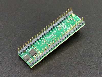
- A female 2×3 2mm header is mounted at the Ethernet connector location on the bottom side of the Teensy 4.1
- Low profile male 5-pin headers are mounted to the bottom side of the Teensy 4.1 to bring down the USB Host, VBat, On/Off and Program buttons.
- Low profile 24-pin headers are installed
By separating the VUSB and VIN power inputs and placing a Schottky diode between them, this allows the Teensy 4.1 to be powered from both the USB cable and VIN input at the same time. It also allows the Teensy 4.1 to be powered on the bench from the USB cable without being placed into a baseboard which can be handy at times.
When using this Teensy 4.1 in a baseboard, it removes the need to try to solder one on which is difficult once the module is built. A diode still needs to be added to the main VIN input power on the baseboard.
Low Profile Specifics:
The female header socket is 3.5mm (0.14″) tall and the contacts have a gold flash.
The male header pin are 2.54mm (0.1″) long with a gold flash and have a 2.5mm (0.1″) tall plastic body.
When these headers are stacked, the combined height is about 6.1mm (0.24″) compared to 11mm for the standard length header/socket combo. This saves about 5mm (0.19″ in height as shown in the picture below. Even with a relatively short contact area, the headers mate with a solid mechanical and electrical connection.
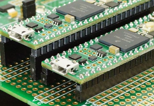
Low Profile Header Comparison to Standard Header
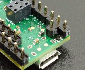
The total stack-up from the baseboard to the top of the Teensy USB connector which is the highest point on the Teensy is 10.6mm as shown below.
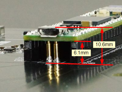
Low Profile Header Stack-up with Teensy
Note: The picture shows spring-loaded POGO pins connecting to the USB pads on the bottom of the Teensy so that the USB can be routed to the edge of the board since the Teensy will be inaccessible in this particular application. In this case, it also allowed the USB connector type to be converted to USB-C. A good POGO pin height for use with these headers is 7.5mm.
Note: The short male header pins as well as bottom mounted I/O prevents this version of Teensy 4.1 from plugging into a standard solderless breadboard. These are typically used with a custom PCB or solder type proto board with the matching mating female sockets.
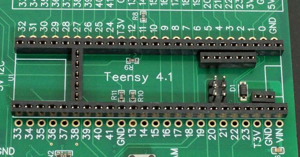
The picture below shows a typical baseboard socket arrangement that this version of the Teensy 4.1 will plug into. The kit that ships with the teensy includes all the female and male headers shown here. If some of the headers are not used, they can be left off and the pins on the Teensy simply left hanging in air. Short headers have less forgiveness on pin alignment than longer standard headers. For installation, you may find it easiest to preinstall the headers onto the Teensy 4.1 first and then solder the entire assembly in place to ensure best alignment.
Memory options
These memory configurations can be selected at the top of the page or down below.
- No Additional Memory
- 8MB/64M-bit PSRAM & 16MB/128M-bit NOR Flash
- 8MB/64M-bit PSRAM & 128MB/1G-bit NAND Flash
- 8MB/64M-bit PSRAM & 256MB/2G-bit NAND Flash
- 16MB/128M-bit PSRAM with no Flash
All memory is installed and tested.
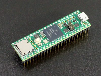
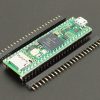
DEV-26-B-LP (Bare with No Added Memory) has all the modifications noted above with no additional memory installed as shown below.
DEV-26-LP (8MB PSRAM/16MB Flash) has an 8MB (64M-bit) volatile PSRAM installed along with a 16MB (128M-bit) non-volatile NOR Flash memory as shown below.
The Flash chip will be a Winbond W25Q128JVSIQ. The PSRAM will be AP 6404L-3SQR or equivalent.
When used with LittleFS file system, the 16MB/128M-bit NOR Flash chip uses the LittleFS_QSPIFlash constructor.
#include “LittleFS.h”
LittleFS_QSPIFlash myfs; // NOR FLASH 128Mb
DEV-26-1G-LP (8MB PSRAM/128MB Flash)has an 8MB (64M-bit) volatile PSRAM installed along with a 128MB (1G-bit) non-volatile NAND Flash memory as shown below for those that need a large amount of non-volatile storage such as for data logging. The NAND Flash is the 8-pad WSON 8x6mm package.
The Flash chip will be a Winbond W25N01GVZEIG. The PSRAM will be AP 6404L-3SQR or equivalent.
When used with the LittleFS file system, the 128MB/1G-bit NAND Flash chip uses the LittleFS_QPINAND constructor.
#include “LittleFS.h”
LittleFS_QPINAND myfs; // NAND FLASH 1Gb
DEV-26-2G-LP (8MB PSRAM/256MB Flash) has an 8MB (64M-bit) volatile PSRAM installed along with a 256MB (2G-bit) non-volatile NAND Flash memory as shown below for those that need an even larger amount of non-volatile storage such as for data logging, image files or audio files. The NAND Flash is the 8-pad WSON 8x6mm package.
The Flash chip will be a Winbond W25N02KVZEIR. The PSRAM will be AP 6404L-3SQR or equivalent.
When used with the LittleFS file system, the 256MB/2G-bit NAND Flash chip uses the LittleFS_QPINAND constructor.
#include “LittleFS.h”
LittleFS_QPINAND myfs; // NAND FLASH 2Gb
DEV-26-P-LP (16MB PSRAM) has two volatile PSRAM chips installed for a total of 16MB (128M-bit) as shown below. There is no external Flash memory installed as the 2nd PSRAM chip physically occupies the Flash location.
The PSRAM will be AP 6404L-3SQR or equivalent.
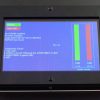
Once assembly is completed, we run test software which is a combination of the PJRC PSRAM and Flash test programs that thoroughly exercises these memory devices.
For full details on the Teensy 4.1 as well as additional compatible parts that may be of interest, please refer to the base Teensy 4.1 Product Page.
Before they are shipped, the Teensy 4.1 has:
- The board is configured as outlined above.
- Board is cleaned of flux
- PSRAM and Flash test software is downloaded and run to verify correct chip operation
- Blink example is downloaded
- Packaged in high quality resealable ESD bag for safe storage.
FURTHER READING:
LEARN – Working with Teensy 4.1 Memory – Overview of the Teensy 4.1 memory architecture including the optional PSRAM and Flash memories.
Notes:
- Because of the bottom mounted I/O and short pins, these Teensy 4.1 will not work in a solderless breadboard.
Technical Specifications
| Microcontroller | NXP iMXRT0162 ARM Cortex-M7 |
| Clock Speed | 600MHz nominal (Optionally 24MHz to 1.008GHz w/ cooling) |
| RAM | 1MB (1024K) |
| FLASH | 8MB (8192K) |
| QSPI PSRAM Chip Location | 8MB PSRAM or empty |
| QSPI Flash Chip Location | 16MB, 128MB or 256MB FLASH or 2nd 8MB PSRAM or empty |
| I/O Logic Levels | 3.3V |
| 5V I/O Compatibility | None |
| Output Pin Drive Current | 10mA |
| DC Current that can be drawn from 3.3V Pin | 250mA maximum |
| Operating Voltage | 3.6 – 5.5V on VIN or VUSB pin |
| Typical Operating Current | 100mA typical @ 600MHz |
| Built-in LED | Attached to digital I/O Pin 13 |
| USB Connector Style | Micro-B Female |
| Board Dimensions (PCB) | 61 x 18mm (2.4 x 0.7″) |
| Country of Origin | USA |
| Mfr | PJRC |
| Datasheet | NXP IMXRT1060 |
| Reference Manual | NXP IMXRT1060 Reference Manual |