Description
Not recommended for new designs or projects.
We recommend use of Teensy 4.0 / 4.1 for new projects. We do not believe supply of chips for Teensy 3.x is likely to ever recover as these chips utilize older fabrication processes.
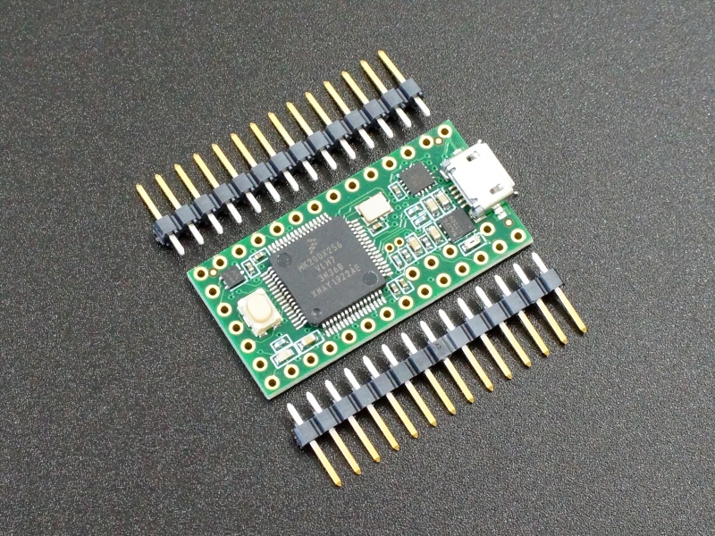
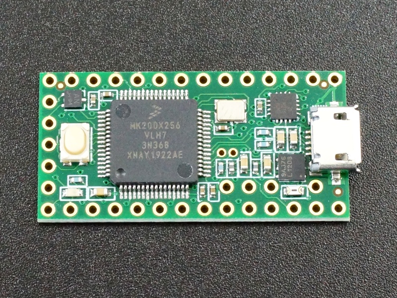
Teensy 3.2 is based on the 32-bit 72MHz ARM Cortex-M4 processor. All digital I/O pins are 5V tolerant. It is formatted into a compact ‘teensy’ board outline for easy embedding into projects or for use with solderless breadboards. Perhaps best of all, it is compatible with the popular Arduino IDE programming environment as well as many of the existing Arduino libraries, so it is very easy to get up and running unlike many other advanced microcontrollers that are available.
Select whether you want with pins soldered or left loose and quantity.
Package Includes:
- Teensy 3.2
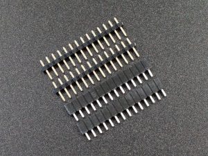
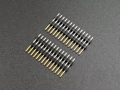
- 1×14 (x2) male headers selectively plated with gold contacts and tin solder pins (Optionally soldered on)
- Handy pinout diagram
KEY FEATURES OF TEENSY 3.2:
- MK20DX256VLH7 ARM Cortex-M4 running at 72MHz with overclock to 120MHz
- 64K RAM
- 256K FLASH
- 2K EEPROM
- 1 USB port
- 1 CAN Bus
- 2 I2S Digital Audio
- 1 SPI with FIFO
- 2 I2C
- 3 serial ports
- 16 general purpose DMA channels
- 12 PWM capable pins
- 34 digital I/O, all interrupt capable
- 24 breadboard friendly I/O pins
- 21 analog input pins with 2 13-bit (usable) ADCs on-chip
- 1 analog output pins with 12-bit DAC resolution.
- 12 touch sensor inputs
- Built-in RTC for date/time
- Compatible with Arduino IDE and many libraries
- Works with Windows, Mac OS X and Linux
- Small size is perfect for embedding or use with solderless breadboards
- 5V tolerant digital I/O
- 3.3V operation
The Teensy product line which is focused on being fast , small and Arduino compatible is developed by the company PJRC. They have a loyal following of designers and advanced hobbyists that create many libraries to take advantage of some of the more advanced features of the Teensy products or to modify Arduino libraries for compatibility. Many of them also participate in the excellent PJRC forum. The forum is targeted towards more advanced users and topics.
What the Teensy 3.2 mainly brings to the party compared to the Teensy 4.0 is 5V tolerance on the I/O which removes the need for possibly dealing with logic level converters and makes it a little more fool-proof than the 4.x line. The Teensy 3.2 is very fast compared to standard Arduino products but not nearly as fast as the Teensy 4.x.
It also has a a nice selection of I/O that includes a 12-bit analog output that the Teensy 4.x lacks. It is a great choice for someone looking to move up in performance from something like an Uno or are getting started with microcontrollers in general and looking for a more capable microcontroller than a typical Arduino as a starting point.
Getting Started with Teensy
Install Arduino IDE Software
To program the Teensy using the Arduino IDE, you must first have the IDE installed if it is not already. If it is installed but not the current version, now is a good time to update to the latest.
Be sure to use the downloaded version of the Arduino IDE which can be downloaded at: https://www.arduino.cc/en/main/software
Install Teensyduino Software
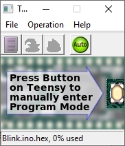
The download and installation instructions can be found at: https://www.pjrc.com/teensy/td_download.html
When Teensyduino is running which it should do automatically, a small window is opened on the desktop. This is the Teensy Loader application that handles the actual download to the Teensy board. Most of the time you can ignore this window as it defaults to Auto Mode which means it will take care of automatically downloading to the Teensy without needing to press the Teensy Program button, but it does need to be running in order to download to the Teensy boards.
Running Blink Program
Once you have the software installed, running the venerable ‘Blink’ program that blinks the on-board LED every second is no harder than a typical Arduino.
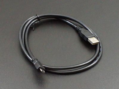
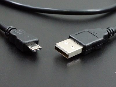
- Attach a Micro-B USB cable to the Teensy
- In the IDE select Tools / Board / Teensyduino / Teensy 3.2
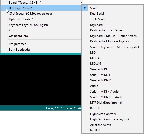
- USB Type should be set to ‘Serial‘
- Select the COM port the Teensy 3.2 is on.
- Open Examples / Basic / Blink
- Press the upload button
The Teensy 3.2 has the on-board LED attached to pin 13 like a typical Arduino.
If the setup is correct, the software will compile and download to the Teensy. The onboard LED should start blinking once per second. Since the board will already have Blink installed when you receive it, you might want to change the timing of the blink to verify the new download was successful.
Important information before going further with using Teensy 3.2
I/O is 3.3V but 5V Tolerant
The Teensy 3.2 operates at 3.3V internally and when driving digital outputs will output a 3.3V signal. This is typically fine for most 5V peripheral devices to detect a logic HIGH level. Digital input levels coming from 5V peripherals will not damage the chip.
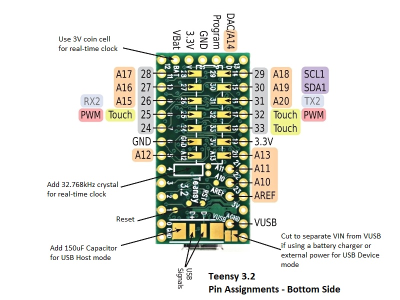
The analog inputs still need to adhere to the 3.3V limitation. This includes A10, A11, A12 A13, A14, AREF, Program and Reset
If you need a Teensy in a larger package with more I/O that is 5V tolerant, the Teensy 3.5 may be a good choice to consider.
Power – One Power Source at a Time!
The Teensy 3.2 can be powered one of 3 different ways, but it is important to note that these are mutually exclusive unlike typical Arduino boards. Internally the module does not provide any power switching between the different power inputs. In essence, if you hook up two different power inputs such as through the USB cable and also through the VIN pin, those two power sources will be shorted together.
USB power (VUSB) – This is typically 5V supplied through the USB cable. A solder pad next to the USB connector also connects to the same VUSB power. An on-board regulator provides 3.3V to power the module
The Teensy 3.2 can also act as a USB Host and supply 5V power coming in on the VIN power input or VUSB pin out the USB port.
VIN pin – External power of 3.6V to 6V can be applied to the VIN pin which also powers the on-board 3.3V regulator to power the rest of the module.
3.3V pin (x2) – These are normally used to power 3.3V peripherals. Total current should be limited to less than 250mA to avoid overheating. Also if you draw too much power and cause the 3.3V to dip down around 3.0V, the CPU will reboot.
External power of 3.3V can also be applied to the 3.3V pins. This bypasses the on-board regulator and powers the module directly. This is the least desirable way to power the module as it bypasses some of the power protection circuitry.
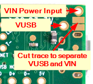
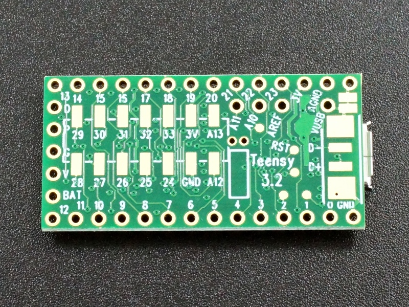
If it is desired to separate the VSUB and VIN power inputs, there is a trace between two large solder pads that can be cut as shown here. If the module is normally powered through VIN, this prevents the USB power from also connecting to the board.
A USB cable can also be modified by cutting the red 5V power wire inside cable, making it a data only cable.
Misc Bits of Info
USB Port
The USB port on the Teensy 3.2 has significant functionality not available on a normal Arduino. For most standard applications it should be set to the default “Serial” mode which is how it works with an Arduino. If you have problems connecting to the Teensy, check this setting.
A quick scan of the menu options available gives an indication of the flexibility of the USB port on Teensy 3.2.
The connector used is the standard Micro-B USB. As with any boards that use this small connector, use care to push/pull the cable directly in and out of the connector and not apply pressure upwards in a lever motion to avoid possible damage.
Program Button
The button on a Teensy board is not a typical reset button like on an Arduino. When pressed, the program button causes the Teensy to enter ‘Programming Mode” where it waits for a download over USB. If the Teensy is connected to the IDE via a USB cable, the last program will automatically be downloaded again and ran.
If the program button is pressed and held for about 15 seconds, the red LED will flash. When the button is then released, the FLASH memory is fully erased and a known good LED blink program is restored into FLASH memory and starts to run. This is a handy way to help restore an otherwise bricked module due to an errant program.
CPU Speed Selection
The Teensy 3.2 nominally operates at 72MHz.
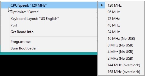
You can select a lower speed to operate at, down to 2MHz, mainly for power sensitive applications. On the other hand you can also potentially overclock the CPU up to 120MHz if adequate heat sinking is provided. Keep in mind that the parts on the board are graded for 72MHz, so performance at clock speeds above that cannot be guaranteed.
Take note that USB will not work at clock speeds of 16MHz or less! It is highly recommended not to drop the clock lower than 24MHz unless you are prepared to work without USB.
The Teensy CoreMark benchmark page has some excellent information on performance, current and temperature over different operating frequencies.
Adding an Audio Adapter
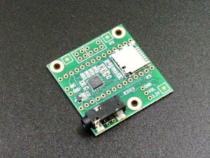
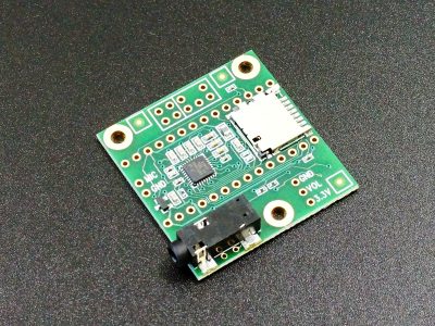
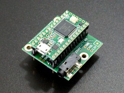
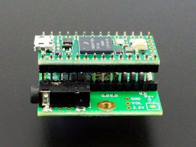
Due to the strong processing power available in the Teensy products, they are a popular target for audio projects whether it is playing multiple WAV files simultaneously, synthesizing music or building sound reactive projects. The Audio Adapter 3.x (Rev C) is designed for the Teensy 3.x product line and supports high quality 16-bit 44.1kHz sample rate (CD quality) audio.
Max: 19 Min: 1 Step: 1 ADD TO CART |
You can find the link to the full Audio Adapter information at the bottom of this page or click on the pic.
Bottom-Side I/O
To make the Teensy 3.2 module as small as possible, some of the I/O (pins 24-33, A12-A13) is brought out to pads on the bottom side of the board. These are designed to be used with POGO pins or surface mounted headers, but can be difficult to work with to get positioning correct.
If you need more I/O than is brought out to the pins on the edges of the Teensy 3.2 module it is generally better to go with the larger Teensy 3.5 if the extra size and cost isn’t a problem.
Assembling the Module
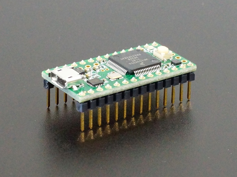
The board ships with high quality selectively plated male headers that are hard to find or they are preassembled onto the module if you order it that way.. They have gold plating on the contact portion of the leg while the solder pins are tin plated for easiest soldering.
The board optionally ships with the male headers loose. This provides maximum flexibility depending on how the board will be used or they can be replaced with other types of connectors such as female headers or shorty headers as shown below. If you are going to be using the module with the Teensy 3.x Audio Adapter in a vertical mount, you may need to install different pins.
To ensure good alignment during soldering first insert the loose headers into a solderless breadboard. The board can then be placed on top of the headers and easily soldered in place.
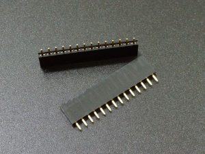
If you want to socket the Teensy 3.2, it can be mated with these 14-pin female headers.
For the vertically challenged, we also offer this complete set of high quality, low profile headers to minimize the stacking height.
Note: Some pics may show the headers unsoldered for mock-up, but the headers must be soldered to make electrical connections.
Our Evaluation Results:
The Teensy line of boards are an excellent product that provides high performance and advanced I/O to tackle even the hardest problems which is why they are often found in advanced hobbyist projects as well as low volume production builds.
The PJRC forum provides access to excellent technical advice that is far more advanced than found on the normal Arduino forums. It is the best place to find information on how to use the advanced features found in the Teensy. It is not the place to get basic Arduino type questions answered however, which is good as the forum is not cluttered with ‘how do I blink an LED?’ type questions.
The Teensy 3.2 is a good solid performer in the lower/middle of the Teensy performance spectrum. If you are brand new to Arduino and programming, you might consider getting your feet wet with a standard Arduino clone board like the Uno first
There are some other Teensy products that may be better suited depending on the application. The Teensy 4.0 has a similar I/O arrangement but has significantly higher performance and more memory but is 3.3V compatible only. The Teensy 3.5 maintains the 5V tolerant I/O in a larger package and runs at 120MHz which is still blistering fast compared to a typical Arduino.
It is highly suggested to checkout the PJRC website and forum at the links below for additional information.
Before they are shipped, these modules are:
- Inspected and tested by PJRC.
- Pins soldered on and flux cleaned if ordered that way.
- Packaged in high quality resealable ESD bag for safe storage.
Further Reading:
PJRC Forum – Excellent source of technical information
PJRC website – Good source of information with many example applications in blog posts.
Board Schematics – Scroll down for different schematics.
Notes:
- None
Technical Specifications
| Microcontroller | MK20DX256VLH7 ARM Cortex-M4 |
| Clock Speed | 72MHz nominal (Optionally 2MHz to 120MHz w/ cooling) |
| RAM | 64K |
| FLASH | 256K |
| Pin Current Output | 10mA |
| I/O Logic Levels | 3.3V |
| 5V I/O Compatibility | Yes on digital I/O |
| DC Current that can be drawn from 3.3V Pin | 250mA maximum |
| Operating Voltage | 3.6 – 6V on VIN or VUSB pin |
| Typical Operating Current | 30mA typical @ 72MHz |
| Built-in LED | Attached to digital I/O Pin 13 |
| USB Connector Style | Micro-B Female |
| Board Dimensions (PCB) | 36 x 18mm (1.4 x 0.7″) |
| Mfr | PJRC |
| Datasheet | NXP MK20DX6256VLH Datasheet |
| Reference Manual | NXP MK20DX6256VLH Reference Manual |

