Tactile Keypad 4X4 Matrix
$1.75
Matrix of 16 tactile pushbutton switches
12 in stock
Description
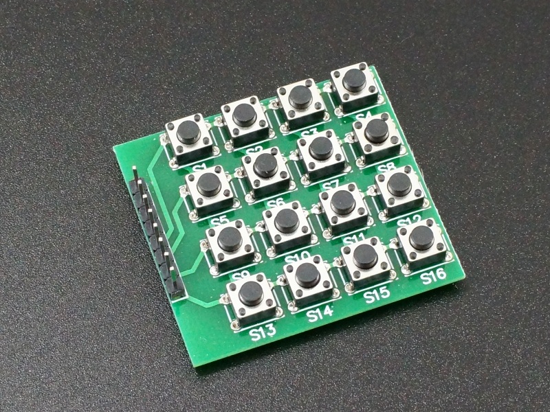
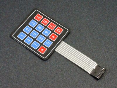
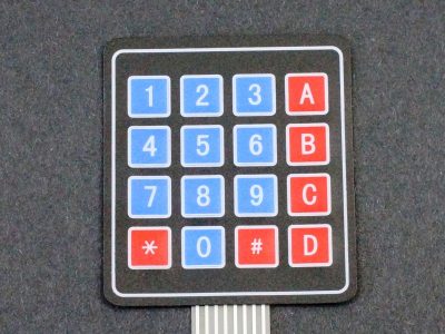
The Tactile Keypad 4×4 Matrix consists of 16 tactile pushbutton switches that provides a convenient and inexpensive way work with a keypad matrix.
PACKAGE INCLUDES:
- Tactile Keypad 4×4 Matrix
KEY FEATURES OF TACTILE KEYPAD 4×4 MATRIX:
- 16 tactile pushbutton switches with good ‘clickability’ mounted on a PCB.
- 3.3 and 5V compatible
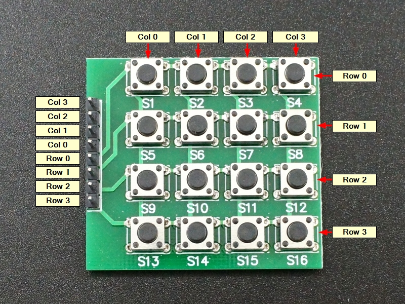
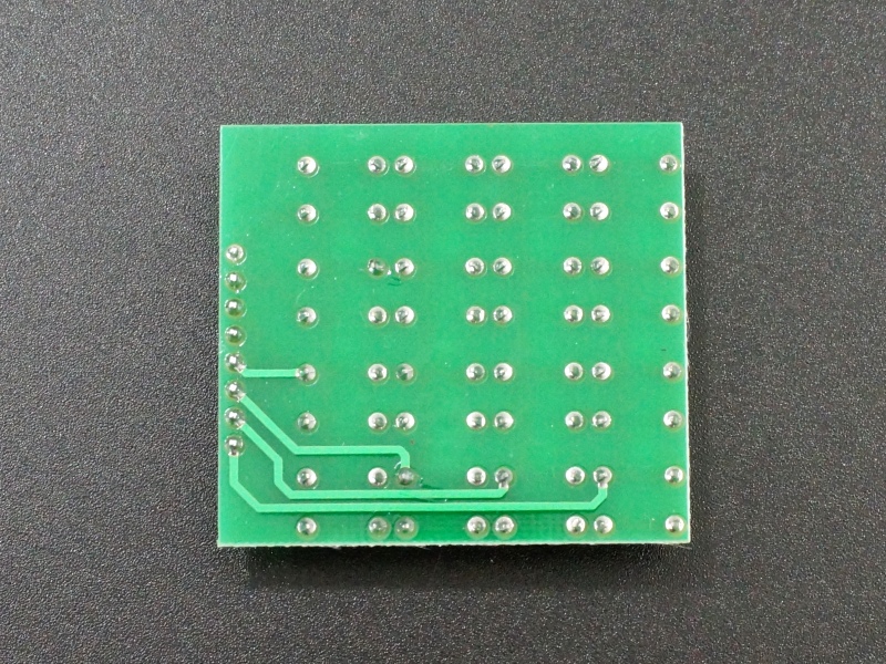
The keypad consists of pushbutton switches that are arranged in a matrix of 4 rows and 4 columns. The pushbutton switches are labeled S1 thru S16 and are wired at the intersection of the rows and columns.
Button pushes can be detected using 8 pins on a MCU. The MCU uses 4 output pins to drive the columns one at a time. At the same time, it uses 4 input pins to scan the rows at the same time. This logic can be inverted so it drives the rows and scans the columns.
When no button is pushed, none of the row/column pins are electrically connected. If a button is pushed, the MCU will see it on an input pin and can determine which button was pushed by which output pin was active when the button push was detected. For example, if the ‘S8’ button is pressed, there will be a short between the Row 1 and Col 3 pins.
Module Connections
The keypad terminates in an 8-pin male header that brings out the 4 row pins and 4 column pins for connection to a MCU.
The header pin-out is shown from top to bottom as you look at the board with the header on the left. Note that the row and column pin order are opposite of each other.
1×8 Header (starting at top)
- Col 3
- Col 2
- Col 1
- Col 0
- Row 0
- Row 1
- Row 2
- Row 3
OUR EVALUATION RESULTS:
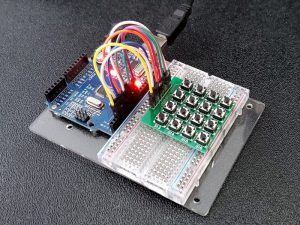
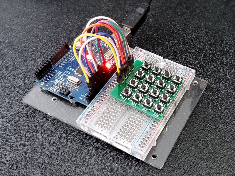
The program below uses the keypad.h library to implement basic functionality of the keypad. The library takes care of all the hard work and basically you just need to get the pins connected correctly between the keypad and MCU. If you run the program and press a button and the wrong key is reported, that most likely indicates a wiring error.
8 pins on the MCU are connected to the keypad. The example uses pins 2 thru 5 for the rows and 6 thru 9 for the columns, but any 8 digital pins can be used if they are redefined in the rowPins and colPins statements below.
Tactile Keypad 4×4 Matrix Example Program
/* Keypad tactile 4x4 Example
Connects to 8 pins defined below.  Can be changed to any digital pins as needed.
Uses Keypad.h library
*/
#include <Keypad.h>

const byte ROWS = 4; // Define the number of rows on the keypad
const byte COLS = 4; // Define the number of columns on the keypad
char keys[ROWS][COLS] = { // Matrix defining character to return for each key
  {'0','1','2','3'},
  {'4','5','6','7'},
  {'8','9','A','B'},
  {'C','D','E','F'}
};
byte rowPins[ROWS] = {5, 4, 3, 2}; //connect to the row pins (R0-R3) of the keypad
byte colPins[COLS] = {9, 8, 7, 6}; //connect to the column pins (C0-C3) of the keypad

//initialize an instance of class
Keypad keypad = Keypad( makeKeymap(keys), rowPins, colPins, ROWS, COLS );
//===============================================================================
//  Initialization
//===============================================================================
void setup(){
  Serial.begin(9600);
}
//===============================================================================
//  Main
//===============================================================================
void loop(){
  char key = keypad.getKey();

  if (key){     // If key is pressed, send it to the Serial Monitor Window
    Serial.println(key);
  }
}
Notes:
- None
Technical Specifications
| Switch Type | 4×4 Matrix | |
| Contact Style | Tactile Pushbutton | |
| Termination Style | Male 1 x 8 header | |
| Dimensions | L x W (PCB) | 43 x 39mm (1.7″ x 1.54″) |

