Membrane Keypad 4X3 Matrix
$0.95
Membrane keypad for providing user input
12 in stock
Description
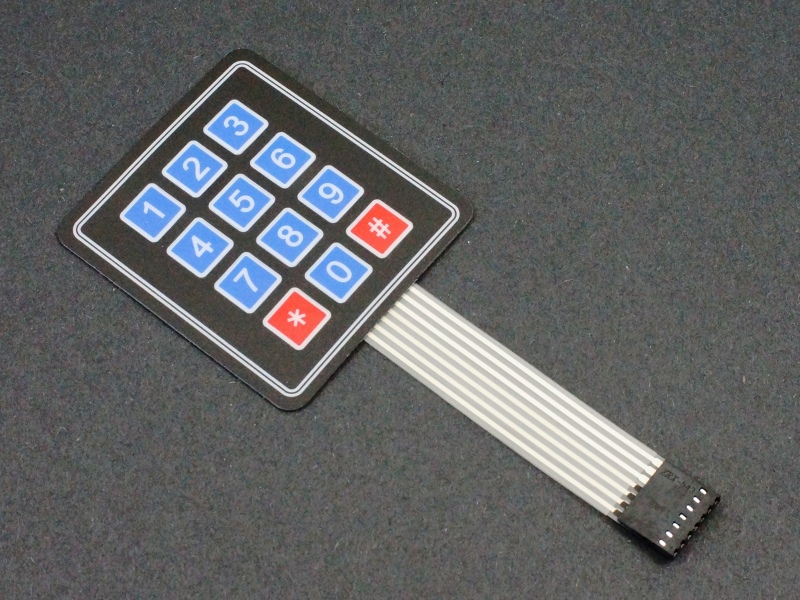
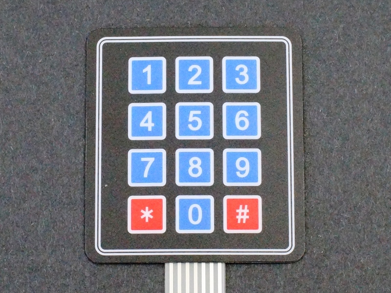
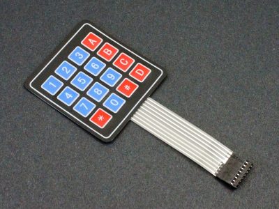
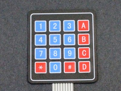
This membrane keypad with an adhesive back has a 4×3 matrix of letters and numbers including 0-9 along with the ‘*’ and ‘#’ symbols..
PACKAGE INCLUDES:
- Membrane Keypad 4×3 Matrix
KEY FEATURES OF MEMBRANE KEYPAD 4X3 MATRIX:
- 12 tactile membrane keys arranged in 4×3 matrix
- Adhesive back for permanently mounting keypad
- 3″ long 8-pin cable terminates in standard 2.54mm (0.1″) female header.
These membrane keypads work well for adding key input for a project. The construction makes them durable and weatherproof.
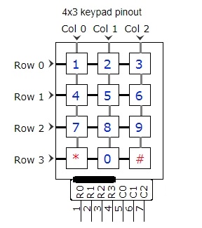
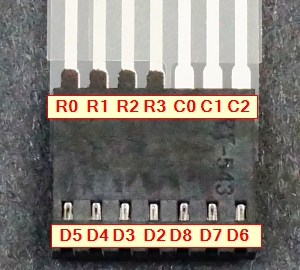
The keypad terminates in an 8-pin cable which has 4 row and 3 column pins. The row pins are on the left as you are looking at the front of the keypad and they have a dark strip near the connector to help identify them. The connector is a standard 2.54mm (0.1″) pitch 1×7 female header.
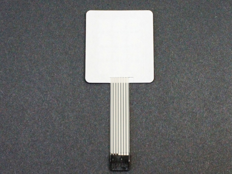
The membrane is a thin but rugged plastic with adhesive on the back. The protective liner can be left in place to keep the keypad mobile or it can be removed and the keypad permanently mounted if desired.
The matrix is resistive which means that when no button is pushed, none of the pins are electrically connected. When a button is pressed, the corresponding Row and Col pins have a resistance of approximately 60-90 ohms between them.
The MCU monitors for key presses by setting a row or column as an output and setting the pins LOW one at a time. It then looks for a LOW logic level on one of the pins on the opposite axis. It does this in a continual scanning process.
For example, if the ‘8’ button is pressed, there will be a low resistance path between the R2 and C1 pins. If the MCU sets R2 as a LOW output and reads C1 as an input, it will see the LOW and know that the ‘8’ button was pressed. These button pushes can easily be detected using 8 pins on an MCU. Software libraries take care of all the messy work as shown in our example below.
Our Evaluation Results:
These keypads are an inexpensive and easy way to add a robust key entry system.
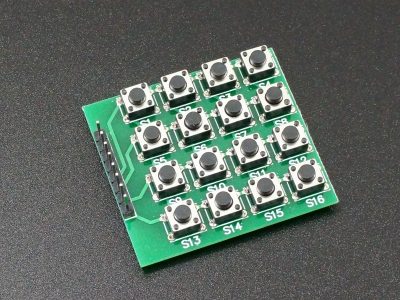
The downside to any type of matrix keypads is that they do consume a fair number of digital pins on the MCU which may or may not be a concern for a particular application. They do consume fewer pins than wiring up the same number of discrete buttons
The program below uses the keypad.h library to implement basic input functionality of the keypad.
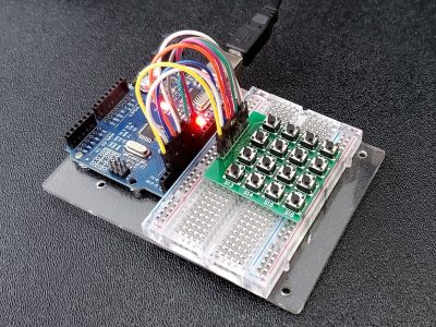
Eight pins on the MCU are connected to the keypad. In this case we are using pins 2-8, but any 8 digital pins can be used if they are redefined in the rowPins and colPins statements below. Wire things up as shown in the picture to the right.
Once the program is downloaded, open the Serial Monitor window using 9600 baud and any key presses should be displayed in the window.
Membrane Keypad 4X3 Matrix Example Program
/* Keypad Membrane 4x3 Example
Connects to 7 pins defined below.  Can be changed to any digital pins as needed.
Uses Keypad.h library
*/
#include <Keypad.h>

const byte ROWS = 4; // Define the number of rows on the keypad
const byte COLS = 3; // Define the number of columns on the keypad
char keys[ROWS][COLS] = { // Matrix defining character to return for each key
  {'1','2','3'},
  {'4','5','6'},
  {'7','8','9'},
  {'*','0','#'}
};
byte rowPins[ROWS] = {5, 4, 3, 2}; //connect to the row pins (R0-R3) of the keypad
byte colPins[COLS] = {8, 7, 6}; //connect to the column pins (C0-C2) of the keypad

//initialize an instance of class
Keypad keypad = Keypad( makeKeymap(keys), rowPins, colPins, ROWS, COLS );
//===============================================================================
//  Initialization
//===============================================================================
void setup(){
  Serial.begin(9600);
}
//===============================================================================
//  Main
//===============================================================================
void loop(){
  char key = keypad.getKey();

  if (key){     // If key is pressed, send it to the Serial Monitor Window
    Serial.println(key);
  }
}
Notes:
- None
Technical Specifications
| Switch Type | 4×3 Matrix | |
| Contact Style | Resistive | |
| Termination Style | Female 1 x 7 header | |
| Dimensions | L x W (Keypad) | 78 x 70mm (3.1″ x 2,75″) |
| Cable Length | 84mm (3.3″) |

