Solid State AC Relay Module 5V x 8
$19.95
3.3 – 5V logic compatible, controls 100-240VAC@2A
5 in stock
Description
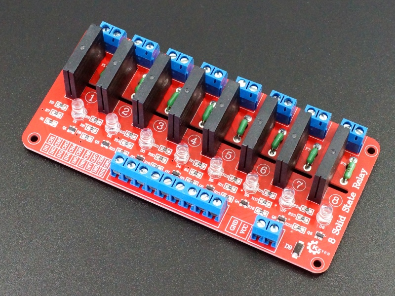
The solid state relay module has 8 independent 3.3V and 5V logic compatible relays that can control up to 120/240VAC@2A
PACKAGE INCLUDES:
- Solid State Relay Module 5V x 8
KEY FEATURES OF SOLID STATE RELAY MODULE 5V X 8:
- 8 independently controlled SSR relays
- Phototriac coupler input isolation
- Switch 100-240VAC @ 2A per relay
- LED indicators when relays are energized
- Built-in snubber circuit
- Zero cross control
- Active HIGH control inputs
- 3.3 and 5V logic compatible
- 5V operation
Solid State Relay (SSR) modules are handy for controlling smaller AC loads.
This module switches up to 8 channels of AC at up to 2A per channel. The solid state relays can turn each AC channel ON or OFF, but it cannot be used for dimming.
Compared to a standard electro-mechanical relay, the solid state relay switches quicker and does not have the long-term mechanical reliability concerns of a standard relay as long as the maximum current limits are observed. The main downside is that it cannot be used to control DC power and max current is limited to 2A.
Module Control
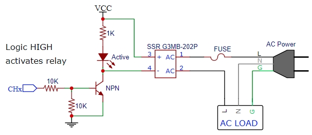
These relays are fully 3.3 and 5V logic compatible. The inputs have a relay driver transistor which means the device needs < 1 mA on the logic control pin to drive it. If you have a microcontroller like an Arduino, you can drive the relays using any of the digital output pins. The relays can also be controlled with mechanical switches or appropriate sensors.
The relays are activated with a logic HIGH signal. There is a red LED that is lit when the control pin for that relay is driven high to activate the relay. A logic LOW deactivates the relay and the LED will go off.
Opto-Isolation
The relays have built-in phototriac couplers on their logic inputs.
These phototriac couplers provide electrical isolation between the logic control input and the relay power as an added layer of protection in case of a major failure on the AC load of the relay.
Module Power
The module requires 4-6V power and ground to operate. The ground must be common with the MCU for the control inputs to work.
The input has a reverse polarity protection diode in case the power connections are accidentally reversed.
When a relay is energized, the relay draws about 10mA from the Vcc pin. With all eight relays energized, the total draw is about 80mA.
Relay Operation
The output of the relay is rated to switch AC power over a maximum range of 75VAC to 264VAC at 2A and suggested range of 100V to 240VAC.
The output is SPST type and is NO (Normally Open). A logic HIGH energizes the relay, so the two output terminals are shorted and power passes through the relay. A logic LOW (or no connection) de-energizes the relay and the output terminals are open.
The relay operates at the zero cross point of the AC waveform so can switch every half cycle or 8.3mS.
Each relay has a 2A soldered in fuse on the AC side for over-current protection.
Module Connections
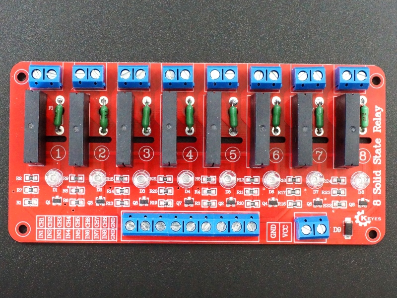
1 x 8 Screw Terminal Block
- IN1/CH1 = Relay control input 1. Logic HIGH level energizes relay 1
- IN2/CH2 = Relay control input 2. Logic HIGH level energizes relay 2
- IN3/CH3 = Relay control input 3. Logic HIGH level energizes relay 3
- IN4/CH4 = Relay control input 4. Logic HIGH level energizes relay 4
- IN5/CH5 = Relay control input 5. Logic HIGH level energizes relay 5
- IN6/CH6 = Relay control input 6. Logic HIGH level energizes relay 6
- IN7/CH7 = Relay control input 7. Logic HIGH level energizes relay 7
- IN8/CH8 = Relay control input 8. Logic HIGH level energizes relay 8
- GND = Ground from MCU or other control input. Tied to Vcc ground on module.
Relay Contacts (2 screw terminal blocks)
- Non-polarized = AC input side of hot lead (typically black wire) connects to one side.
- Non-polarized = Load side of hot lead connects to the other side.
1×2 Power Screw Terminal Block
- VCC = 4-6VDC (5V typical)
- GND = Vcc power Ground
OUR EVALUATION RESULTS:
These are nice relatively inexpensive modules that will work for a number of applications where lower power AC devices of up to about 220W @ 110V need to be controlled. For a terrarium setup for instance, the module could automatically control the lights, heat lamp, heat rock, mister, circulating fan and similar devices. Control of Christmas lighting is another popular type of application.
When switching AC power, proper safety should be observed to ensure the wiring is secure and not easily contacted to avoid an electrical shock. These are often built into a electrical box with a terminal strip to make the AC electrical connections in a safe and secure manner.
Note that unlike mechanical relays, SSR relays cannot be operated in parallel to increase their current handling capability. This is because the relays will not turn on at exactly the same time and the first one to turn on will carry the full load until it fails or the fuse blows and then the second one will turn on and also subsequently fail.
For redundancy purposes, it is possible to operate 2 is parallel if the load is within the 2A limit of a single relay. If the relay carrying the load fails, the other relay will automatically switch on.
BEFORE THEY ARE SHIPPED, THESE MODULES ARE:
- Sample inspected and tested per incoming shipment.
- Repackaged in high quality resealable ESD bag for safe storage.
FURTHER READING:
Example application – Great Houdini Escape Room
Notes:
- None
TECHNICAL SPECIFICATIONS
| Logic Input | @ Vcc = %V | |
| Logic High | > 2.5V | |
| Unknown State | 1.0V – 2.5V | |
| Logic Low | < 1.0V | |
| Drive Current | < 1mA | |
| Vcc | Voltage Range | 4-6VDC (5V typical) |
| Maximum Current | 10mA per relay, 80mA with all relays energized | |
| Relay Rating | Maximum | 75-264VAC @ (0.1 – 2A) |
| Recommended | 100-240VAC @ (0.1 – 2A) | |
| Max Inrush Current | 30A (8.3mS) | |
| Relay Type | Omron | G3MB-202P |
| Dimensions | L x W x H | 128 x 61 x 25mm (5 x 2.4 x 1″) |


