PC817 Optocoupler
$0.35
Provide electrical isolation of a signal between 2 circuits by using an optical bridge.
32 in stock
Description
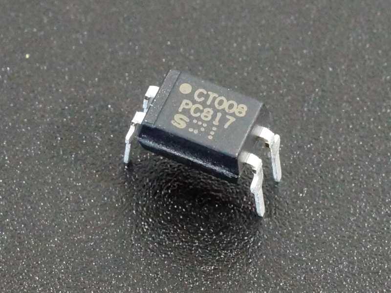
The PC817 Optocoupler is used to provide electrical isolation of a signal between 2 circuits by using an optical bridge.
PACKAGE INCLUDES:
- PC817 Optocoupler
KEY FEATURES OF PC817 Optocoupler:
- Small 4-pin DIP package
- High 5kV electrical isolation between input / output
- High output voltage up to 80V
- Up to 50mA output current
Optocouplers, also called Photocouplers or Opto-isolators consist of a combination of an infrared LED and a phototransistor in a single package that is used to optically couple an electrical signal through the device without using an electrical connection. The device is uni-directional and can only pass a signal in one direction.
Optocouplers are used to provide electrical isolation between two points in a circuit. Most often, they are used in a digital circuit to provide electrical isolation between a uC and a high energy output circuit such as a motor or to provide an additional layer of protection when using something like a relay to control a high energy device. They work by blocking any electrical spikes that might otherwise find their way back down the line to the uC.
Inserting one of these in line with a uC pin will help to protect that pin, but in order to fully isolate two parts of a circuit, it also requires that separate power systems be used on the two sides of the circuit so that there are no electrical sneak paths back through the power system. This is typically over-kill for most hobby applications, but something to consider when full isolation is desired.
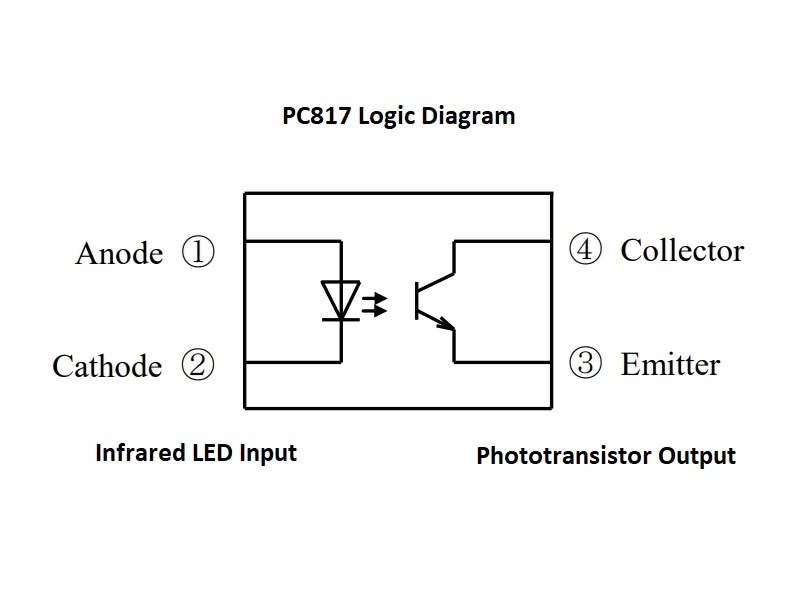
Internally, the device has an IR LED on one side and a phototransistor on the other side of the device. Driving the LED causes the base of the phototransistor to also be driven, thus turning on the phototransistor.
Current Limiting Resistors
When hooking up the device, two resistors are required to provide current limiting on the two sides of the device to prevent damage.
The first is a current limiting resistor on the IR LED input side of the device. The absolute maximum current through this LED is 50ma, but in practice the current should be limited to no more than 20mA for safe use with a uC. A resistor value of 470 ohms which gives a current of 10ma will work for most applications as a staring point. A larger resistor can be used if lower current is desired or if the drive voltage for the IR LED is higher than 5V.
The second resistor is similarly used to limit the current flow through the phototransistor. The max current is again 50ma, but it is typically operated at a lower current. Depending on what the optocoupler is being used to interface to, typically either a pull-up resistor is used that connects between the collector of the optocoupler and the power (Vcc) that is being used on the output side of the circuit or a series resistor is used that is connected between the emitter and the base of a transistor if a transistor is being used on the output. A 470 ohm resistor can usually be used as a starting point for this resistor as well.
OUR EVALUATION RESULTS:
These devices can be very useful for adding a level of protection when a uC needs to interface with scary type circuits or when long cables are involved that may pick-up electrical spikes.
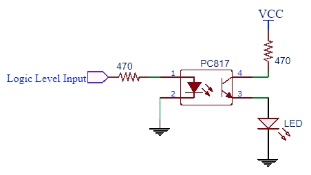
The circuit below is useless, but it demonstrates the basic operation of the device. A logic HIGH on the input should light the LED on the output.
Notes:
- None
Technical Specifications
| Maximum Ratings | ||
| IF | Maximum Forward Current (Input) | 50mA |
| IF Collector | Maximum Forward Current (Output) | 50mA |
| VF | Collector – Emitter | 80V |
| Package Type | Plastic body, DIP-4 | |
| Mfr | China | |
| Datasheet | Typical | PC817 |

