ADuM1201 Dual Channel Digital Isolator Module
$2.59
Provides electrical isolation and logic level conversion
36 in stock
Description
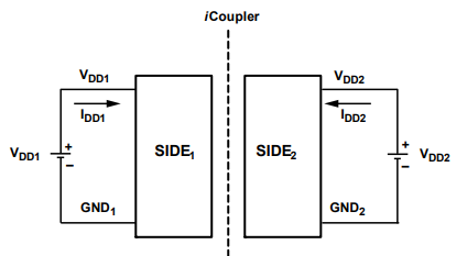
The ADuM1201 is a dual channel digital isolator using technology by Analog Devices called iCoupler. It provides electrical isolation similar to an optocoupler and optionally provides logic level conversion between 3.3V and 5V systems.
PACKAGE INCLUDES:
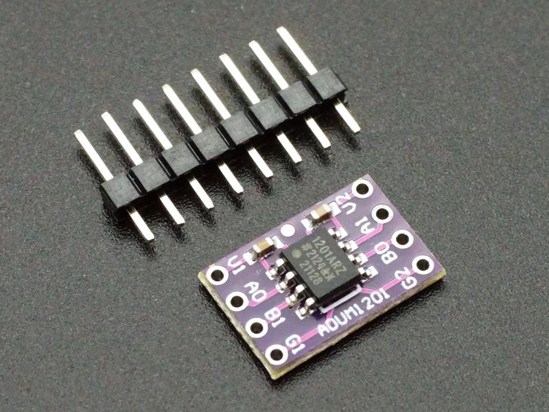
- ADuM1201 Dual Channel Digital Isolator Module
- 8-pin male header strip
KEY FEATURES OF ADUM1201 DUAL CHANNEL DIGITAL ISOLATOR MODULE:
- 1 Input and 1 Output channel ideal for serial links
- Chip scale transformers provide 2500Vrms isolation
- Convert logic levels between 3.3V and 5V
- Operates up to 1Mbps
When working with digital I/O between different systems that have different grounds, these modules isolate the two power systems and prevent ground loops where ground current flows from one system to another. They also prevent transients on the serial lines in electrically noisy environments from damaging components such as the microcontroller.
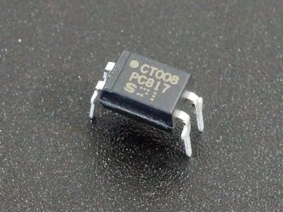
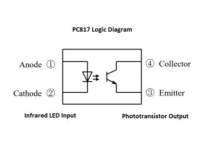
Compared to common optocouplers, the iCoupler magnetic technology requires less current to operate so can easily be driven by low current sources and doesn’t require current limiting series or pullup resistors. It has shorter propagation delays and good symmetry between the inbound and outbound channels.
These are most often used for serial TTL data level isolation and/or level conversion because they have both an output (TX) and input (RX) channel on the single device. They can also be used for other generic logic level conversion and isolation purposes.
Module Operation
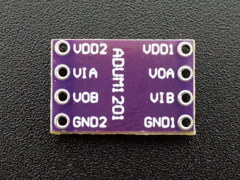
The module has two separate power system connections. VDD1 and GND1 (pins V1 & G1) are used on one side of the module and would come from one power system, such as the microcontroller power system while VDD2 and GND2 (pins V2 & G2) are used on the other side of the module and would come from a second power system such as the serial device power system in order to provide complete electrical isolation.
Each of the two power connections has a bypass capacitor included on the module.
Both sides of the module support a voltage range of 2.7V to 5.5V which allows for logic level conversion between 3.3V and 5V systems should that be required. If the module is being used for logic level conversion only without providing isolation, both the 3.3V and 5V can come from the same power system and the grounds can be common.
Module Connections
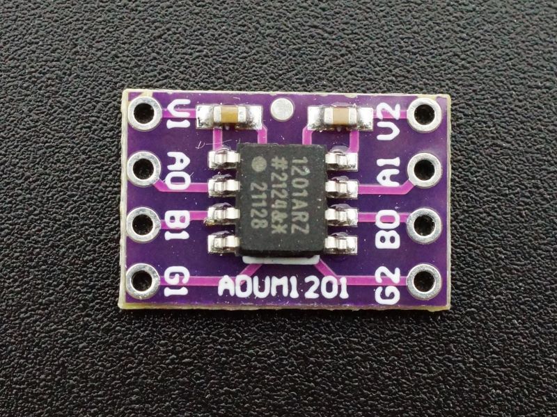
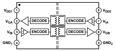
The module is laid out to mirror the chip pinout. The drawing and pin labes above is from the datasheet. The pin labels used on the module itself are shown below
The module has the following I/O connections:
- V1 = 2.7 – 5.5V from power system 1 (VDD1)
- AO = Channel A Output (VOA)
- BI = Channel B Input (VIB)
- G1 = Ground for power system 1 (GND1)
- G2 = Ground for power system 2 (GND2)
- BO = Channel B Output (VOB)
- AI = Channel A Input (VIA)
- V2 = 2.7 – 5.5V from power system 2 (VDD2)
If using for logic level conversion only, V1 and V2 can come from the same power system and the grounds can be common. Both ground pins must be connected.
ASSEMBLING THE MODULE
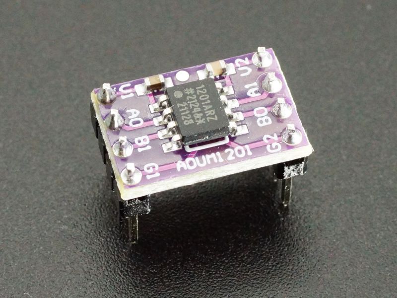
The module comes with a strip of straight male headers. This can be broken in half and soldered on for use with a breadboard, or you can use right-angle headers or attach wires directly to the board depending on what your application requires.
To ensure good alignment during soldering first insert the loose headers into a solderless breadboard. The board can then be placed on top of the headers and easily soldered in place.
OUR EVALUATION RESULTS:
These little modules nicely fill the niche of adding isolation, especially to serial communication lines that are going off-board.
BEFORE THEY ARE SHIPPED, THESE MODULES ARE:
- Sample tested per incoming shipment.
Notes:
- None
Technical Specifications
| Operational Ratings | ||
| V1, V2 | 2.7V – 5.5V | |
| Maximum Drive Current | 1.1mA | |
| Maximum Data Rate | 1Mbps | |
| Dielectric Insulation Voltage | 2500Vrms | |
| Dimensions | L x W (PCB) | 10 x 15.3mm (0.39″ x 0.60″) |
| Footprint | DIP-8 on 0.5″ centers | |
| Country of Origin | China | |
| Datasheet | Analog Devices | ADuM1201ARZ |
FURTHER READING

