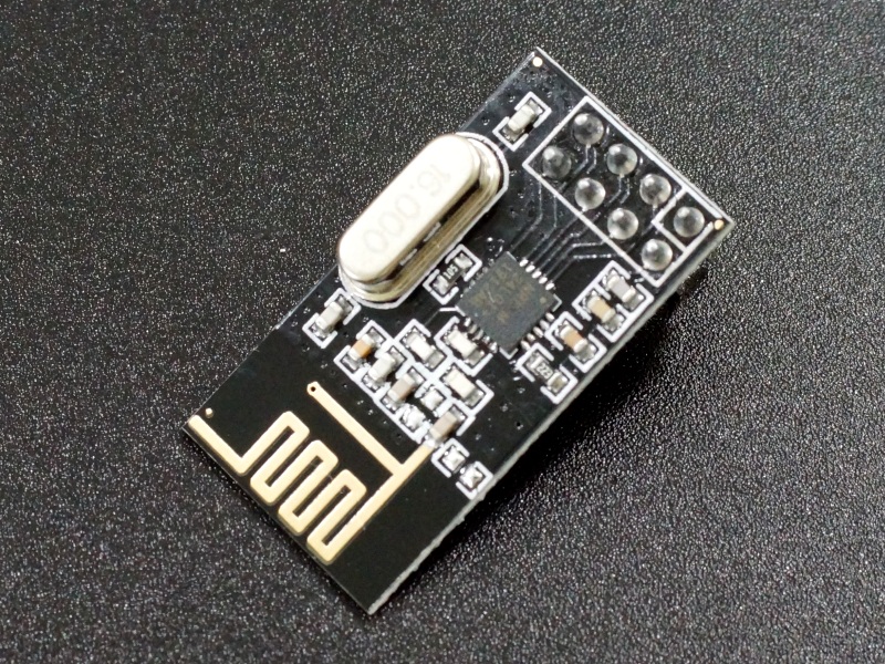
nRF24L01+ 2.4GHz RF Wireless Module
$1.69
RF Wireless Module has a range up to 100 meters and up to 2Mbps data rate.
38 in stock
Description
The nRF24L01+ are low power RF transceiver modules that can be used for wireless communications at up to 100 meters.
PACKAGE INCLUDES:
- nRF24L01+ 2.4GHz RF Wireless Module
KEY FEATURES OF nRF24L01+ 2.4GHz RF WIRELESS MODULE:
- 2.4GHz Operating Band
- 100 meters Operating Range
- 125 RF Channels
- 250Kbps – 2Mbps Data Rates
- 3.3V Operation
The modules operate in the 2.4GHz band at data rates of 250Kbps, 1Mbps or 2Mbps and at a range of up to 100 meters. Max operating current is < 14mA.
The module can use up to 125 different channels spaced 1Mhz apart which cover the frequency spectrum from 2.400GHz to 2.525GHz. This gives the possibility to have a network composed of up to 125 independently working transceivers. Each channel can have up to 6 addresses, or each module can communicate with up to 6 other modules at the same time. Networks can be configured as Star and Tree networks.
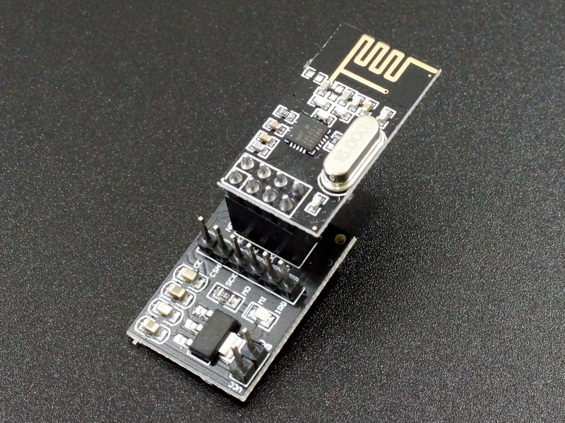
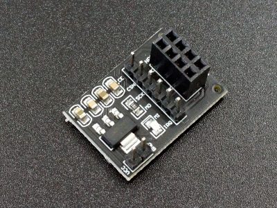
The module operates at 1.9V – 3.6V, but the I/O is 5V tolerant, so it can be directly connected to a 5V Arduino or other microcontroller without using any logic level converters. The module power can be driven off the 3.3V power pin, or it can be used with our adapter module below which takes 5V in and has a built-in 3.3V regulator. The adapter also provides pin-out labels, power LED and power supply filtering.
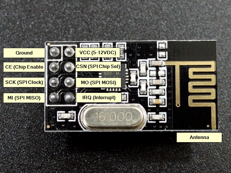
The module uses 5 signal pins in addition to the power and ground pins. Communications with the module use the SPI bus which is composed of 3 pins (MOSI, MISO, SCK). These pins connect to the same SPI pins on the microcontroller. The other 2 pins (CSN, CE) that are used for setting the module into standby/active mode as well as switching between transmit or command mode and these can be attached to any 2 digital pins on the microcontroller. In addition, there is an interrupt pin which isn’t typically used.
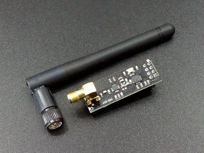
If a longer range is required, our NRF24L01+PA+LNA w/ antenna module can reach up to 1100 meters.
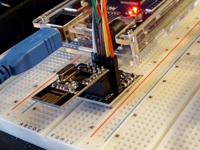
The module has a 2×4-pin header on the assembly. See pic for layout as the boards may not have the pins labeled.
2 x 4 Header
- GND – Ground. Connect to ground on microcontroller
- VCC – 1.9 – 3.6V. Typically connected to 3.3V on the microcontroller unless adapter module is being used.
- CE – Chip Enable. Sets whether module is in RX or TX mode.
- CSN – SPI Chip Select
- SCK – SPI Clock
- MOSI – SPI Slave Data Input
- MISO – SPI Slave Data Output
- IRQ – Maskable Interrupt
Our Evaluation Results:
If driving the modules directly off of the 3.3 Arduino power, the typical recommendation is to use the minimum power setting or to supply some additional filter capacitance if using high power mode. In practice, we haven’t noted any power systems issues when using the modules in high power mode directly off the Arduino and the power looks clean on an O’scope, but that is when using our test software which isn’t overly strenuous on the modules. More demanding applications may see issues.
If our adapter is used (available below), that will ensure that the power to the module is as good as it can be since it includes its own built-in 3.3V regulator and filter caps.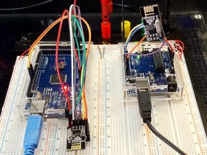
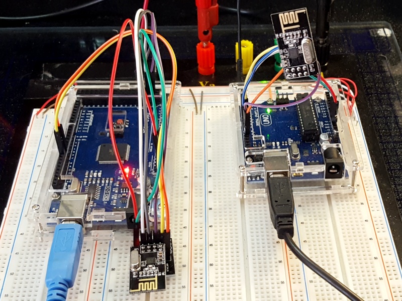
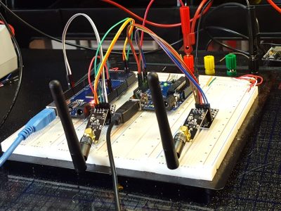
The examples below setup a simple one-way link between a transmitter and receiver using any two Arduinos or similar microcontrollers. The transmitter continually increments a number and transmits the numbers to the receiver that dutifully displays them in the Serial Monitor window.
It uses the RF24 library which can be downloaded using the Arduino IDE.
The modules require 3.3V power and ground which can come from the Arduino. If you are using our adapter module, you can use the 5V instead.
The SPI interface signals are hardwired to specific pins on the different Arduino boards so you will use the pins associated with the boards that you are using. Here is a table of some common pinouts. Note that these SPI pins are also available on the ICSP header if the board has one. In some cases, like the Leonardo, these pins are only available on the ICSP header.
| SPI (SCK) | SPI (MOSI) | SPI(MISO) | |
| Uno | 13 | 11 | 12 |
| Mega | 52 | 51 | 50 |
| Nano | 13 | 11 | 12 |
| Pro Micro | 15 | 16 | 14 |
| Leonardo | ICSP-3 | ICSP-4 | ICSP-1 |
The final 2 connections are the control lines CE (sets RX or TX mode of operation) and CSN (Chip Select). these can be any 2 I/O lines. In our examples, we use pins 7 for CE & 8 for CSN, but these can be changed to other pins if needed. You just need to reassign them, do so in the statement: RF24 radio(7, 8);
Transmitter Device Software
/*
 * nRF24L01 Transmitter Test Software
 *
 * Exercises the nRF24L01 Module.  This code runs on the transmitter 'Master' device.
 * Use the nRF24L01_Receiver_Test software for the receiving 'Slave' device
 *
 * This uses the RF24.h library which can be installed from the Arduino IDE
 * Pins used for the SPI interface are determined by the Arduino being used.
 * The other two pins are arbitrary and can be changed if needed.  Redfine them in the RF24
 * statement.  Default shown here is to use pins 7 & 8
 */
#include <SPI.h>
#include <nRF24L01.h>
#include <RF24.h>
RF24 radio(7, 8); // CE, CSN      // Define instance of RF24 object called 'radio' and define pins used
const byte address[6] = "00001";  // Define address/pipe to use.
unsigned long count = 0;                   // Use to count the number of messages sent
char countStr[10];                 // Create a char array to hold count as a string
//===============================================================================
//  Initialization
//===============================================================================
void setup()
{
  radio.begin();                  // Start instance of the radio object
  radio.openWritingPipe(address); // Setup pipe to write data to the address that was defined
  radio.setPALevel(RF24_PA_MAX);  // Set the Power Amplified level to MAX in this case
  radio.stopListening();          // We are going to be the transmitter, so we will stop listening
}
//===============================================================================
//  Main
//===============================================================================
void loop()
{
  count++;                              // Increment the count
  ltoa(count,countStr, 10);             // Convert the count and put into the char array.
  char text[30] = "Sending Message: ";  // Create our base message.
  strcat (text, countStr);              // Append the count to the base message
  radio.write(&text, sizeof(text));     // Write the char array.

  delay(1000);                          // Delay for 1 second, then repeat
}
Receiver Device Software
/*
 * nRF24L01 Receiver Test Software
 *
 * Exercises the nRF24L01 Module.  This code runs on the receiver 'slave' device.
 * Use the nRF24L01_Transmitter_Test software for the transmitting 'master' device
 *
 * This uses the RF24.h library which can be installed from the Arduino IDE
 * Pins used for the SPI interface are determined by the Arduino being used.
 * The other two pins are arbitrary and can be changed if needed.  Redfine them in the RF24
 * statement.  Default shown here is to use pins 7 &
 */
#include <SPI.h>
#include <nRF24L01.h>
#include <RF24.h>
RF24 radio(7, 8); // CE, CSN      // Define instance of RF24 object called 'radio' and define pins used
const byte address[6] = "00001";  // Define address/pipe to use. This can be any 5 alphnumeric letters/numbers
//===============================================================================
//  Initialization
//===============================================================================
void setup() {
  Serial.begin(9600);                // Start serial port to display messages on Serial Monitor Window
  radio.begin();                     // Start instance of the radio object
  radio.openReadingPipe(0, address); // Setup pipe to write data to the address that was defined
  radio.setPALevel(RF24_PA_MAX);     // Set the Power Amplified level to MAX in this case
  radio.startListening();            // We are going to be the receiver, so we need to start listening
}
//===============================================================================
//  Main
//===============================================================================
void loop() {
  if (radio.available()) {
    char text[32] = "";               // Clear buffer
    radio.read(&text, sizeof(text));  // Read incoming message into buffer
    Serial.println(text);             // Print the message to the Serial Monitor window
  }
}
Before they are shipped, these modules are:
- Sample inspected and tested per incoming shipment
Notes:
- None
Technical Specifications
| Operating Ratings | ||
| Vcc | Range | 1.9 to 3.6V (3.3V Typical) |
| Imax | 12mA | |
| Band | 2.4GHz | |
| Data Rates | 250Kbps / 1Mbps / 2Mbps | |
| RF Channels | 126 | |
| Output Power | Programmable | 0, -6, -12 or -18dBm |
| Dimensions | L x W (PCB) | 29mm x 15mm (1.1 x 0.6″) |
| Country of Origin | China | |
| Datasheets | nRF24L01+ Nordic |
Further Reading

