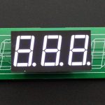
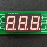
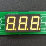
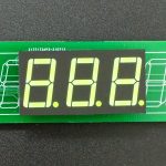
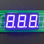
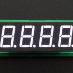
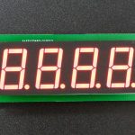
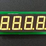
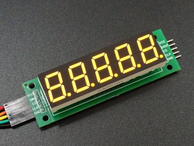
MAX7219 0.56″ 3 or 4-Digit 7-Segment Display Board
$4.95
Supports common cathode LED modules over SPI bus
103 in stock
Description
Easily assemble your own 7-segment display module customized to your requirements.
You can add the number of boards you need to your cart and then select from the additional optional items like LED modules down below if you need them.
PACKAGE INCLUDES:
- PSA-1: MAX7219 0.56″ 3 or 4-Digit 7-Segment Display Board
KEY FEATURES OF MAX7219 0.56″ 3 or 4-DIGIT 7-SEGMENT DISPLAY BOARD:
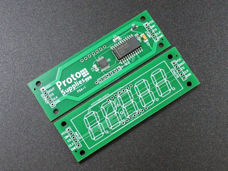
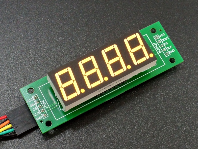
- Supports a 0.56″ Common Cathode 12-pin 7-segment LED display module
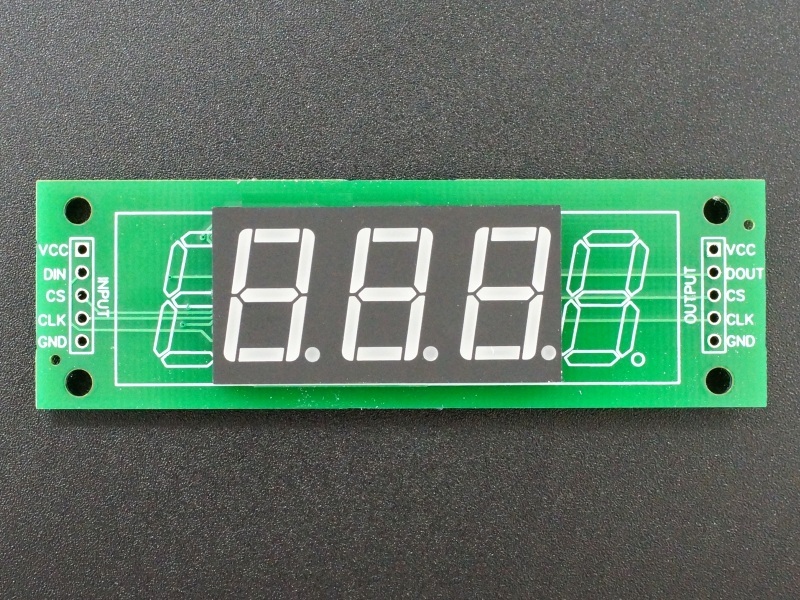
- Supports 3 or 4 digits with floating decimal point
- Reverse polarity protection
- MAX7219 LED Driver
- 74HCT125 buffered data and loop-thru
- SPI 3-wire serial interface for easy hookup to MCU
- Link up to 8 boards together
- Fully 3.3V and 5V logic compatible
- 5V operation
7-segment displays have been around for a long time and are still popular for many applications where numeric information needs to be displayed. They work especially well in situations where there may be strong ambient lighting, such as outdoors.
Some common uses include displaying voltage and current on a variable power supply, keep an electronic score or create a reaction timer display. They are also popular for duplicating the look of displays found in airplane cockpits for home-built flight simulators.
Unfortunately, wiring a system using the raw 7-segment LED modules from scratch is difficult and the available premade modules which use 8-digits, while inexpensive, don’t usually fit the requirements.
For that reason, we have created our own 7-segment display boards that are easy to use by integrating the popular MAX7219 LED driver chip that allows up to 8 display modules to be daisy-chained and controlled using just 3 pins on the MCU. They are fully 3.3V and 5V logic compatible so that they can be directly connected to any MCU.
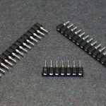
The hard work has been done on these modules by incorporating all the surface mount components. You just need to add a couple of easy to solder thru-hole parts to customize the final assembly to your requirements. Since the same board will support different display sizes and colors, the board can be socketed so that the LED configuration can be changed on the fly which can be useful for experimenting with different configurations. They work best with the female round machined sockets rather than standard female headers due to the size of the LED pins.
Theory of Operations
These modules utilize the popular MAX7219 LED control chip which has very good library support for most MCUs which makes them easy to implement in a project. The chip works with common cathode LED display modules and handles all aspects of maintaining the display, so the MCU only has to update data on the displays when needed. The chip can program the LED brightness, blank digits and support a decimal point per digit.
The MAX7219 communicates via the SPI interface in write-only mode so it only needs 3 pins from the MCU. If using software SPI as used in our example below, these can be any 3 digital pins on the MCU.
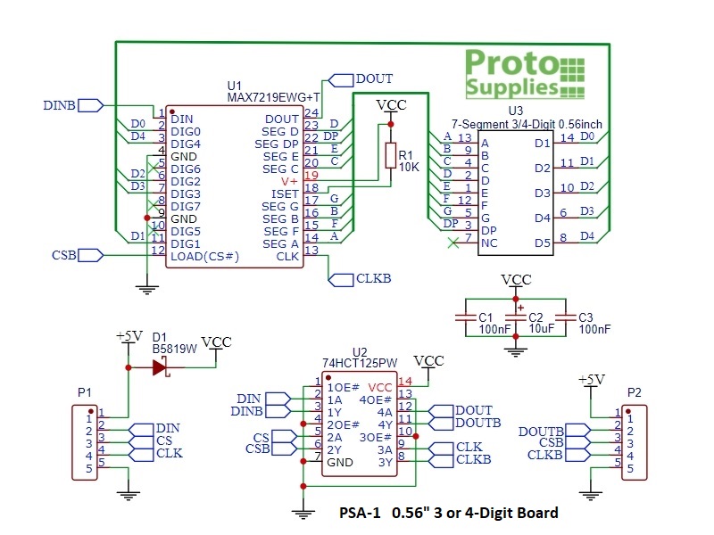
Normally MAX7219 chips cannot be reliably driven directly by 3.3V logic due to their higher than normal minimum logic high voltage (Vih) requirement of 3.5V. These modules include a 74HCT125 logic level buffer chip to drive the MAX7219 correctly from either 3.3V or 5V logic. This buffered signal is also passed to the loop-out connector for connection to other display modules so the MCU only sees one signal load.
The modules include reverse power protection diodes on each module. The loop-thru power does not include this diode drop to allow multiple modules to be daisy-chained together mainly limited by the size of the wiring used between modules and the size and brightness of the displays used . For longer daisy -chains, the power can be connected at several points in the chain if needed.
The power input includes a 10uF tantalum and 0.1uF MLCC capacitors at the chips to minimize voltage fluctuations during display operation.
IMPORTANT NOTE: The module is wired so that the left most digit is Digit 0. This allows the same PCB to be used with 3 or 4digit displays giving maximum flexibility. When using fewer than 4 digits, the LED display is offset to the left side on the board i.e. pin 1 is always pin 1. If using with 3rd party software, check to be sure that won’t be an issue.
Module Connections
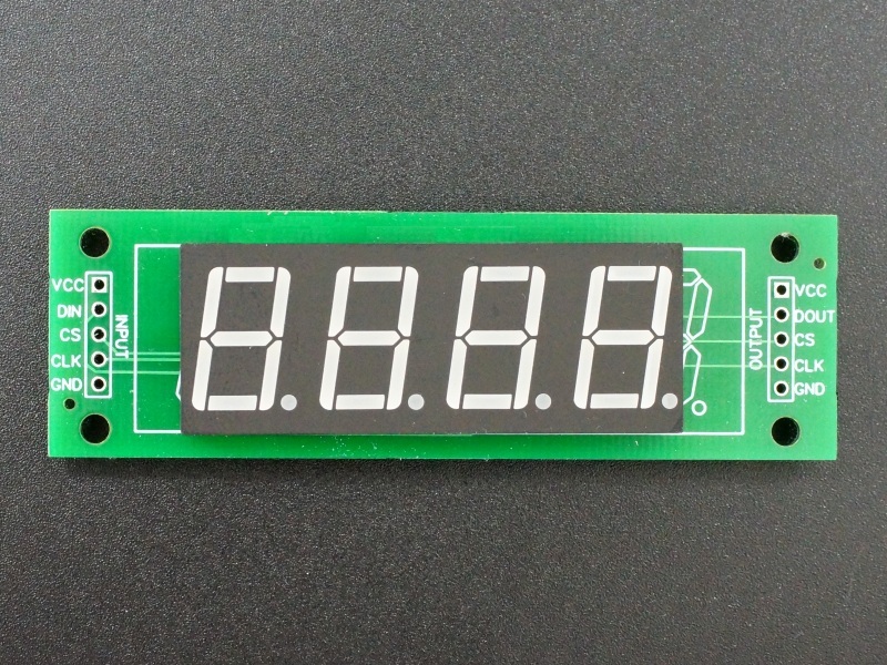
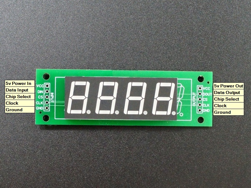
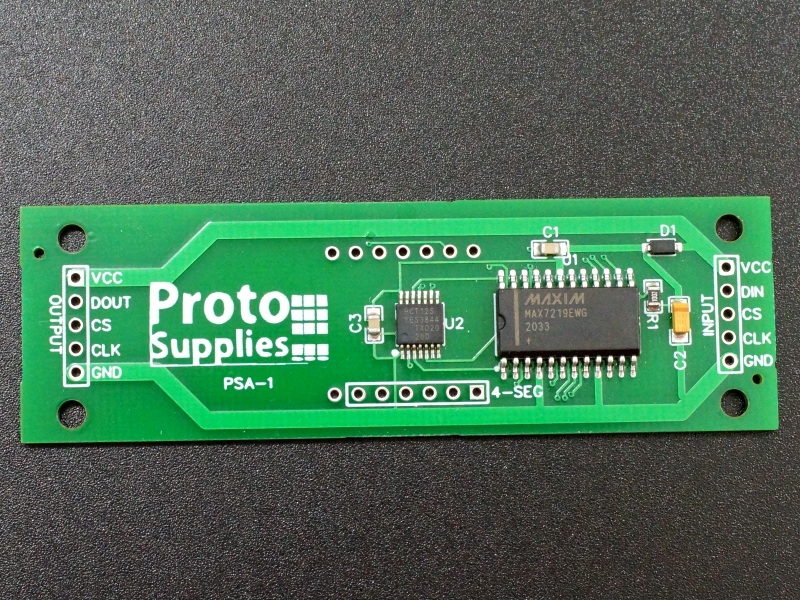
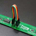
There are two 5-pin header locations on the assembly.
Input Connector
The header pins on the left end is the main input connector. “VCC” connects to 5V. “GND” connects to ground which needs to be common with the MCU.
The other pins are for the SPI interface. “DIN” is the Data In. “CS” is Chip Select (sometimes labeled as LOAD) and “CLK is the Clock pin. These 3 pins are connected to the corresponding SPI pins on the MCU or can be any digital outputs on the MCU if using software SPI as we do in our example below.
1 x 5 Header
- VCC – Connect to 5V.
- DIN – SPI MOSI
- CS – SPI Chip Select
- CLK – SPI Clock
- GND – Connect to system ground. This ground needs to be common with the MCU.
Output Connector
The header pins on the right end of the assembly are used if it is desired to daisy-chain displays. In this case, the “DOUT” is Data Out and it connects to the next modules “DIN” Data In pin. The other pins are passed straight-thru. All data lines are buffered by the 74HCT125.
1 x 5 Header
- VCC – Connect to 5V on next module if looping power through.
- DOUT – Buffered Data Out. Connect to DIN on next module.
- CS – Buffered Chip Select. Connect to CS on next module
- CLK – Buffered Clock. Connect to CLK on next module
- GND – Connect to GND on next module
Assembly
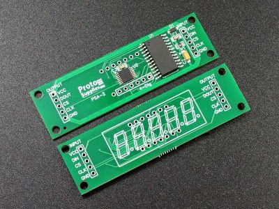
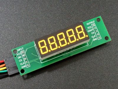
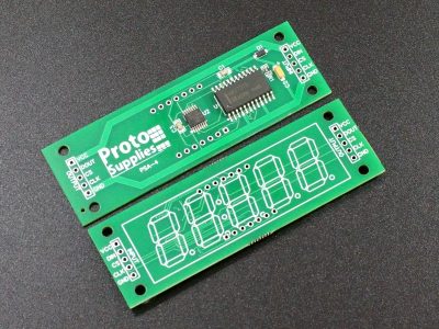
Although the silkscreen shows 5-digits, this board supports either 3 or 4 digit displays. The board was originally designed to also support 5-digit modules, but the desired LED modules could not be sourced. A separate board, the PSA-4 is used to mount the 5-digit displays.
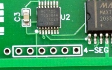
If using sockets for the LEDs, be sure to use the machined round female type as sold below and not the regular female headers like are found on an Arduino Uno. The regular female headers will not provide a good electrical connection to the small round pins on the LED module and intermittent display operation is likely.
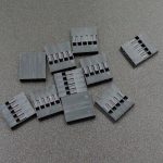
In some applications where space is tight and the board wont physically fit, individual wires can be run from the display board to the pins on the LED module so the board can be remotely mounted. If you want these to be unpluggable for easier build and servicing, installing straight male headers in the LED pin locations on the board will allow standard Dupont style female connectors to be used for connections to the board. If you use female connectors on the other end without the housing, they can be slipped over the pins of the LED and soldered in place for a robust permanent connection.
Straight or right-angle headers can be installed on either the top or bottom of the board for the I/O connections. In most cases it will make sense to install them on the bottom. Right angle headers are handy for using the modules flat on a table for experimenting while straight headers exiting the back will minimize the required space between two adjacent boards when installed into a project if that is important.
Installation
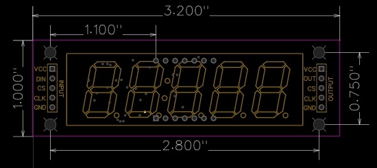
The boards have four M3 (0.118″) size mounting holes in the corners on 2.8 x 0.75″ centers. The LED module display will be offset somewhat relative to the board.
Board drawings can be found at the bottom of the page.
User Added Parts to Configure the Modules
The items in this section can be added to the order if they are needed to finish the configuration of your displays. Click on pics for more info about each item.
To avoid overpowering the camera, the pictures are taken with the LEDs turned down as far as they will go. Brightness and color saturation is not an issue with these displays.
3-Digit 0.56″ CC LED Modules:
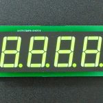
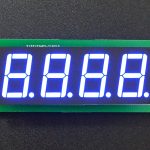
4-Digit 0.56″ CC LED Modules:
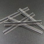
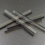
Misc Hardware:
USING THE MODULE:
IMPORTANT NOTE: The module is wired so that the left most digit is Digit 0. This allows the same PCB to be used with either 3 or 4 digit displays giving good flexibility. The LED display is offset to the left side on the board i.e. pin 1 is always pin 1.
Example programs tend to assume Digit 0 is on the right, so if using one of these canned programs, you may need to reorder the way the digits are written to the display which is easy to do.
If using the popular LedControl library for instance, when writing an ‘8’ to the first (right most) digit of a 4-digit display with no decimal point, instead of writing lc.setDigit(0,0,8,false); it would be lc.setDigit(0,3,8,false);
While the LedControl library works well, it is a bit clunky to use since you have to write each digit separately. The program below provides a framework for using these displays very easily with the LedControl library.
The subroutine DspNumber is where the magic happens. It accepts a number of parameters and uses recursion to display the number and to place the decimal point if one is to be shown.
void DspNumber(long number, int dsp = 0, byte pos = LEDSIZE – 1, boolean dp = false, byte dpPos = 0)
number = The number to write to the display.
dsp = The display in the chain to write the number on. First display is 0.
pos = Position of right-most digit to start writing the number. 3-digit display = 2, 4-digit display = 3, 5-digit display = 4.
dp = True/false flag as to whether to show a decimal point.
dpPos = position of that decimal point if it is to be shown.
DspNumber uses default argument values which can be useful to minimize the number of parameters that need to be passed. These are easily customized for a particular application. For instance, if you have a single 3 digit display with 1 digit always to the right of a decimal point i.e. XX.X, the subroutine can be changed to:
void DspNumber(long number, int dsp = 0, byte pos = LEDSIZE – 1, boolean dp = true, byte dpPos = 1)
The calls can then be made using just DSPNumber (number); since all the other parameters can use the default arguments.
To use the program below, set these 2 lines near the top of the program to match your setup.
The first defines the pins to use for controlling the module and the number of modules that are attached. These are software SPI pins, so can be any convenient 3 digital pins. Parameters are (DataIn, Clk, CS, # displays)
LedControl lc=LedControl(5,7,6,2);
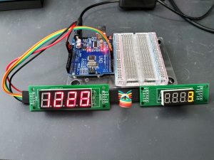
In our case here (DataIn pin = 5, Clk pin = 7, CS pin = 6, and we have 2 displays attached)
The second line defines the number of digits in the displays we are using (3-5). We are using 4-digit displays in our example.
const int LEDSIZE = 4;
If you plan to mix displays with different number of digits in a project, it may be easiest to create an instance of the LedControl for each of the different sizes used, running one chain for 4-digit displays and another chain using 3 different MCU pins for 5-digit displays for instance. Mixing physical sizes such as 0.36″ and 0.56″ size LEDs won’t make any difference.
The program first writes 8’s to all of the displays and then moves a decimal point across each of the displays in turn. It then counts down from 9 to 1 on all displays.
Finally, it does a counter function to count up from 0 to 999 or 9999 or 99999 on the first display depending on how many digits the displays have. If there is a 2nd display attached, it will display the number of loops the counter has made on it. A delay(5); is used in the loop to slow down the counting. If using this with a fast Teensy for instance, all digits are pretty much a blur otherwise.
MAX7219 7-Segment LED Module Example
/*
  MAX7219 7-segment LED Module test

  This program is used to test ProtoSupplies.com 7-Segment display modules
  and also provides a good starting point for using these displays in a system

  To allow the same baseboard to support 3, 4 or 5 digit displays, the left-most
  digit is considered digit 0 which is the opposite of how most software is
  setup.

  This program does the following:
  - Writes 8's to all connected displays, then moves a decimal point across all.
  - Displays all 9's to all 1's on all displays.
  - Continually counts up on the 1st display 0-999, 0-9999 or 0-99999 then loops.
  - If a 2nd display is connected, it is used to show the loop count.

  Based on the LedControl library that can be installed from the IDE library manager

  The subroutine DspNumber is where the magic happens
*/
#include "LedControl.h"
// Our example assumes we have two 4-digit displays connected

// Define pins for LedControl. These can be any digital pins on microcontroller.
// LedControl(DataIn, Clk, Load/CS, # of MAX7219 in chain)
LedControl lc = LedControl(5, 7, 6, 2);

const int LEDSIZE = 5;  // # digits in LED modules we are using

long num = 0;           // Variable to hold counter number
int loopCnt = 0;        // Variable to hold loop count number

/*===============================================================================
   Subroutine - DspNumber (number, dsp, pos, dp, dpPos)

   number = number to display
   dsp = display to write the number on in the MAX7219 chain (0-7)
   pos = position of first digit to write.  3 digits=2, 4 digit=3, 5 digit=4
   dp = boolean flag whether to show a decimal point
   dpPos = position to put the decimal point if there is one to show.

   Default argument values can be useful to minimize the number of arguments that
   need to be passed if items such as the decimal point or LED size do not change.
   If you always want one digit to right of decimal point change dp=true, dpPos=1
   as an example
  =============================================================================== */
void DspNumber(long number, int dsp = 0, byte pos = LEDSIZE - 1,
               boolean dp = false, byte dpPos = 0) {

  byte digit = number % 10;           // Get first digit on right

  if (dp && dpPos == pos)             // Check if DP needs to be displayed
    lc.setDigit(dsp, pos, digit, true); // Display digit with DP
  else
    lc.setDigit(dsp, pos, digit, false); // Display digit without DP

  long remainingDigits = number / 10; // Check if another digit to display
  if (remainingDigits > 0) {          // If there is, do it all again
    DspNumber(remainingDigits, dsp,  pos - 1, dp, dpPos);
  }
}
//===============================================================================
//  Initialization
//===============================================================================
void setup() {
  // Initialize all displays
  for (int dsp = 0; dsp < lc.getDeviceCount(); dsp++) {
    lc.setScanLimit(dsp, LEDSIZE); // Limit scan to size of LED module
    lc.shutdown(dsp, false); // Wakeup display
    lc.setIntensity(dsp, 2); // Set brightness to a lower level (1-15)
    lc.clearDisplay(dsp);   // Clear the display
  }

  // Display all 8's and move a decimal point around all attached displays
  // Any extra digits over LEDSIZE will not be displayed
  for (int dsp = 0; dsp < lc.getDeviceCount(); dsp++) {
    DspNumber( 88888, dsp, LEDSIZE - 1);
  }
  delay(1000);
  for (int dsp = 0; dsp < lc.getDeviceCount(); dsp++) {
    DspNumber (88888, dsp, LEDSIZE - 1, true, 0);
    delay (1000);
    DspNumber (88888, dsp, LEDSIZE - 1, true, 1);
    delay (1000);
    DspNumber (88888, dsp, LEDSIZE - 1, true, 2);
    delay (1000);
    DspNumber (88888, dsp, LEDSIZE - 1, true, 3);
    delay (1000);
    DspNumber (88888, dsp, LEDSIZE - 1, true, 4);
    delay (1000);
    DspNumber (88888, dsp, LEDSIZE - 1, false, 4);
  }
  // Display all digits from 9's to 1's on all attached displays
  for (long iL = 99999; iL > 0; iL = iL - 11111) {
    for (int dsp = 0; dsp < lc.getDeviceCount(); dsp++) {
      DspNumber (iL, dsp);
    }
    delay (1000);
  }
  for (int dsp = 0; dsp < lc.getDeviceCount(); dsp++) {
    lc.clearDisplay(dsp);   // Clear all displays
  }
}
//===============================================================================
//  Main
//===============================================================================
void loop() {
  // Continually count up on first display in chain.
  DspNumber (num);  // Using default argument values so only need number to display
  num++;
  delay(5);  // Slow things down a bit

  // If max displayable value reached, reset count and clear the display
  if ((LEDSIZE == 3 && num > 999) || (LEDSIZE == 4 && num > 9999) || (LEDSIZE == 5 &&
      num > 99999)) {
    num = 0;
    lc.clearDisplay(0);   // Clear the display
    // Count loop interations on 2nd display if one is attached
    if (lc.getDeviceCount() > 1) { // We have 2nd display, so display loop count
      DspNumber(++loopCnt, 1);
      if ((LEDSIZE == 3 && loopCnt > 999) || (LEDSIZE == 4 && loopCnt > 9999) ||
          (LEDSIZE == 5 && loopCnt > 99999)) {
        loopCnt = 0;
        lc.clearDisplay(1);
      }
    }
  }
}
Notes:
- The back of the board contains the electronics, so some care should be used to avoid possible shorting if placed on a metallic surface.
Technical Specifications
| Display Type | 0.36″ | 3 or 4 digits, Common Cathode, 12-pin |
| Operating Ratings | DC Power Input range | 4.0 – 5.5 VDC |
| Display refresh rate | 800Hz (typical) | |
| Reverse polarity protection | Yes | |
| Dimensions | ||
| PCB (L x W) | 81.3 x 25.4 mm (3.2 x 1.0″) | |
| Mounting holes (L x W) | 71.1 x 19mm (2.8 x 0.75″) | |
| Character Height | 14.2mm (0.56″) | |
| Country of Origin | Designed in USA | Manufactured in China |
| Datasheet | MAX7219 | |
| 74HCT125 |
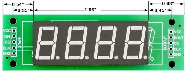
LED 7-Segment 0.56 x 4 Dimensions
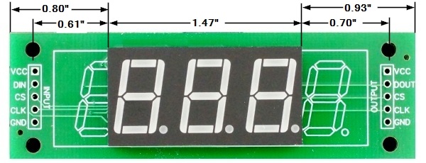
LED 7-Segment 0.56 x 3 Dimensions

