Joystick Module
$1.59
2-axis analog outputs based on position of joystick
38 in stock
Description
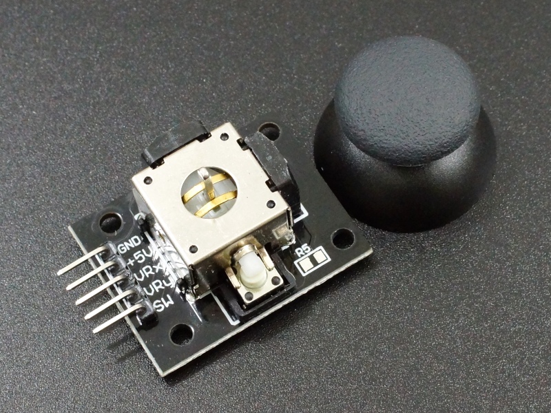
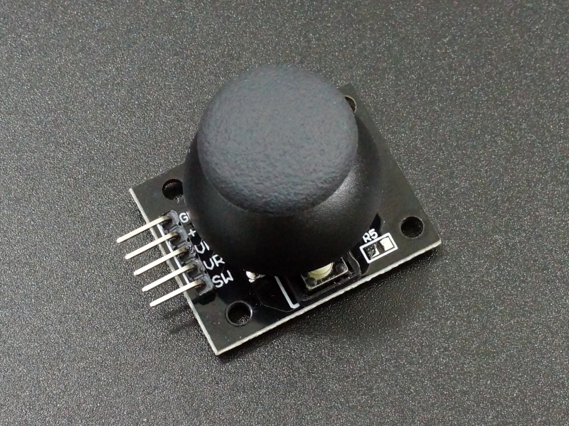
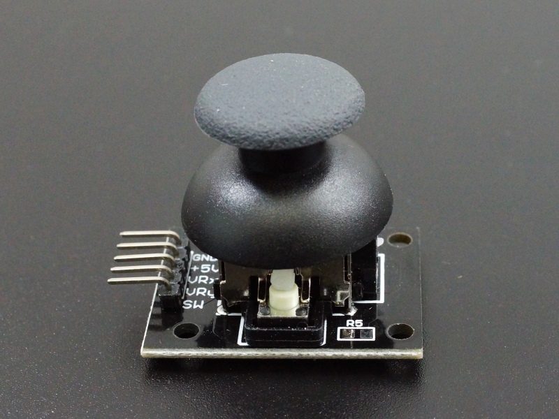
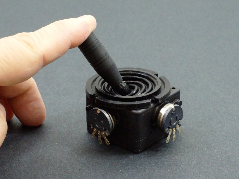
The Joystick Module provides 2-Axis analog outputs based on the X/Y position of the joystick as well as a pushbutton activation when the joystick is pressed.
PACKAGE INCLUDES:
- Joystick Module w/ snap-on cap
KEY FEATURES OF JOYSTICK MODULE:
- 2-Axis analog outputs based on the X and Y position of the joystick
- Pushbutton action when joystick is depressed
- 3.3 and 5V compatible
The joystick module is a fully functional joystick similar to what is found on many game controllers and can be used for a number of different control applications such as for controlling a robotic system.
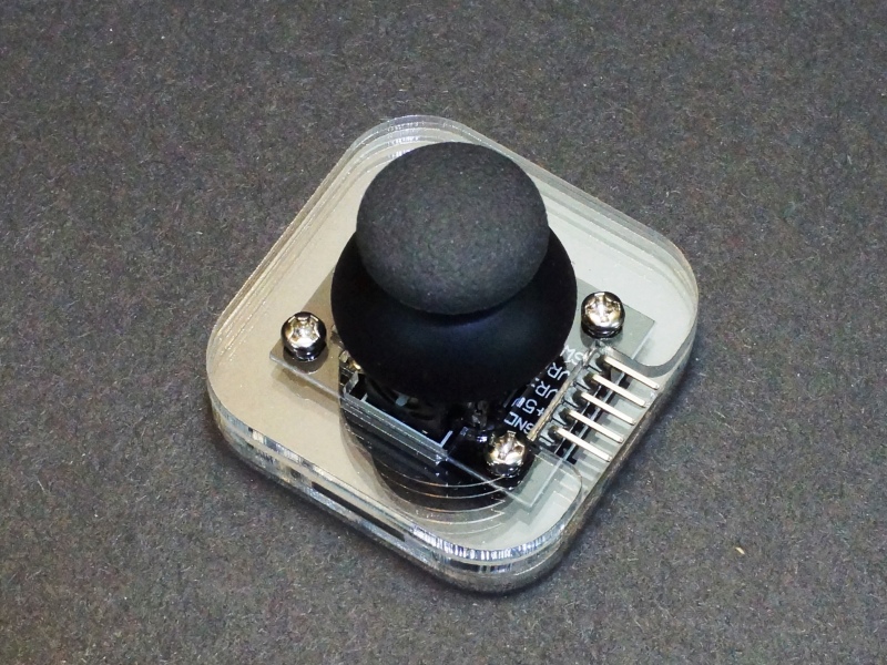
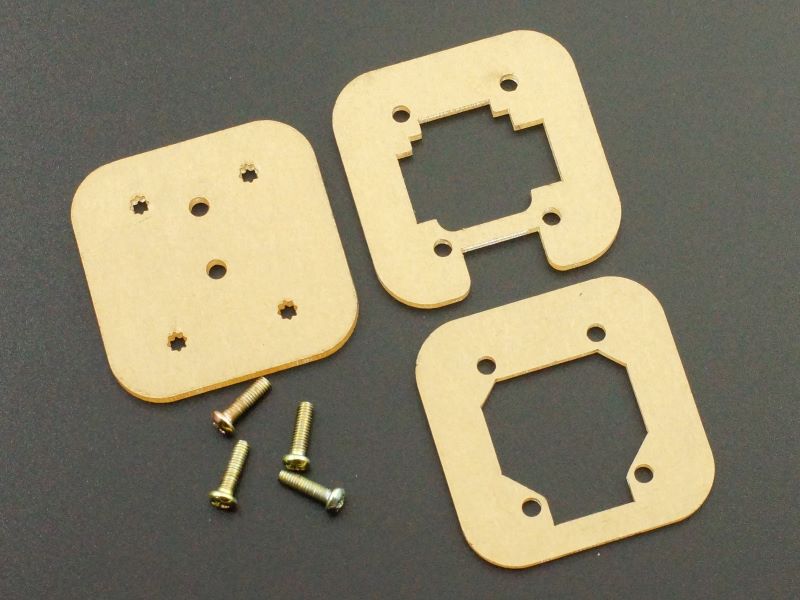
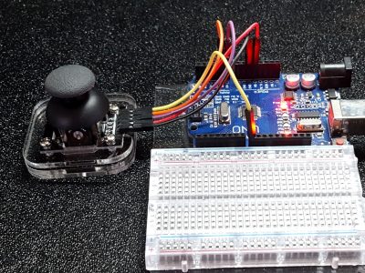
An acrylic base is also available at the bottom of the page.
Joystick Controls
The module includes two spring loaded 5K potentiometers that provide X and Y analog outputs which can be input to two analog inputs on an MCU. There is also a push button switch output if the cap is pressed down until an audible click is heard. The pushbutton output can be connected to any digital input pin of an MCU.
For reference, the X-Axis is motion parallel to the header pins on the module while the Y-Axis is motion perpendicular to the header pins.
The analog inputs on an MCU read values over a range of 0-1023 (for typical 10-bit ADC inputs). The X-Axis and Y-Axis controls should read around 512 (midpoint) when the control is at rest. As the joystick is moved, one or both of the controls will register higher or lower values depending on how the control is being moved. When the joystick is released, it is spring-loaded and will return to center.
The switch output is grounded (LOW) when the switch is pushed. When the switch is at rest, the output is floating, so a pull-up resistor is needed to pull the output high. When using with an MCU, the input pin that the switch is connected to should have the built-in pull-up enabled or else an external pull-up resistor can be used.
Module Connections
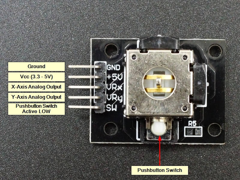
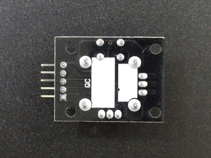
There is a 5-pin header on the assembly for making connections.
1 x 5 Header
- GND = Ground
- +5V = Vcc (3.3 – 5V)
- VRx = Analog X-Axis output. Connects to analog input on MCU
- VRy = Analog Y-Axis output. Connects to analog input on MCU
- SW = Switch Output, active LOW. Connects to digital input on MCU
OUR EVALUATION RESULTS:
These modules are low cost construction but quite useful and fun to play with in a number of applications both for general experimenting as well as integrating into a final application such as for robotic control.
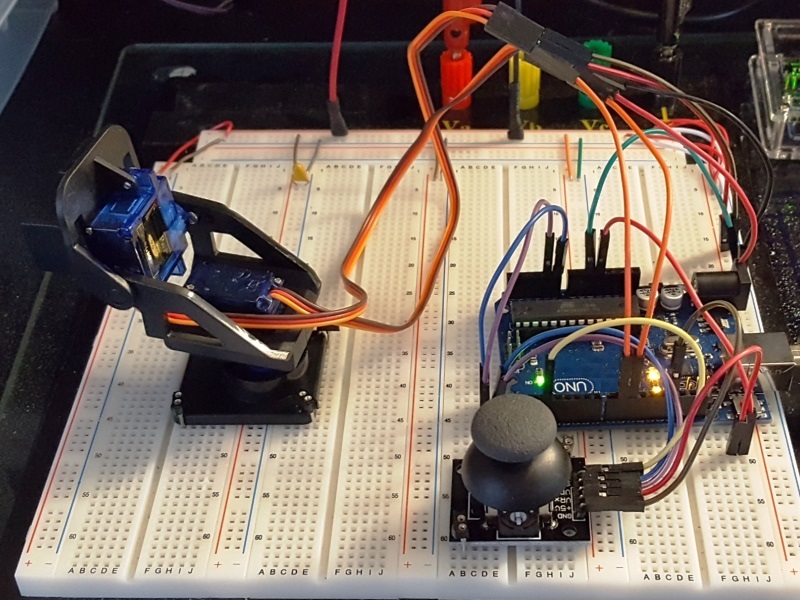
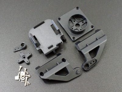
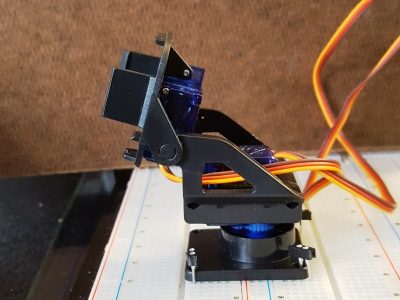
This short video shows one of these joysticks controlling a 2-Axis motorized mount. The software being used for this app can be found on the 2-Axis motorized mount product page linked down at the bottom.
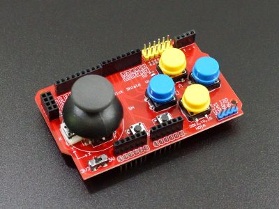
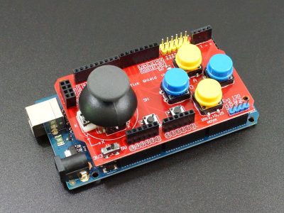
If you are looking for an integrated joystick along with buttons on an Arduino shield format, checkout the Funduino Shield down below.
The program below illustrates and tests the basic functionality of the module. It reports the current state of the X-Axis, Y-Axis and pushbutton controls out to the Serial Monitor window.
The program uses analog pins A0 and A1, but these can be any 2 analog pins. The button can be attached to any digital pin. Be sure to enable the internal pull-up resistor on the digital pin or else add an external pull-up resistor. A 10K or 4.7K resistor is typically used for pull-ups, but the value is not important in this application.
Joystick Module Test Program
/*
Joystick Module Test

Basic code for monitoring the outputs of the module.
*/
int xPin = A1;      // Use any analog input pin to read X-Axis pot
int yPin = A0;      // Use any analog input pin to read Y-Axis pot
int buttonPin = 2;  // Use any digital input pin to monitor button

int xPosition = 0;  // Variable to hold current X-Axis reading
int yPosition = 0;  // Variable to hold current Y-Axis reading
int buttonState = 0;// Variable to hold current button state
//===============================================================================
//  Initialization
//===============================================================================
void setup()
{
  Serial.begin(9600);

  pinMode(xPin, INPUT);
  pinMode(yPin, INPUT);
  pinMode(buttonPin, INPUT_PULLUP);   // Enables pull-up resistor on button pin
}

//===============================================================================
//  Main
//===============================================================================
void loop()
{
  xPosition = analogRead(xPin);         // Read the current state of all 3 controls
  yPosition = analogRead(yPin);
  buttonState = digitalRead(buttonPin);

  Serial.print("X: ");                  // Print current state out to Serial Monitor window
  Serial.print(xPosition);
  Serial.print(" | Y: ");
  Serial.print(yPosition);
  Serial.print(" | Button: ");
  Serial.println(buttonState);

  delay(250);    // add some delay between reads.  Using long delay to make easier to read
                 // output on screen.  This delay would be shorter to improve responsiveness in
                 // live application.
}
BEFORE THEY ARE SHIPPED, THESE MODULES ARE:
- Sample inspected and tested per incoming shipment
Notes:
- This is similar to or the same as the KY-023 module.
Technical Specifications
| Operating Ratings | Vcc Range | 3.3 – 5V |
| Analog Outputs | 0 – Vcc | |
| Pushbutton Output | Active Low | |
| Dimensions | L x W (PCB) | 40 x 22mm (1.6 x 0.9″) |

