IR Obstacle Avoidance Sensor Module
$1.25
Uses an infrared emitter / receiver pair to detect obstacles
12 in stock
Description
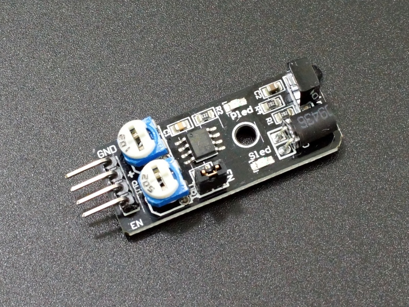
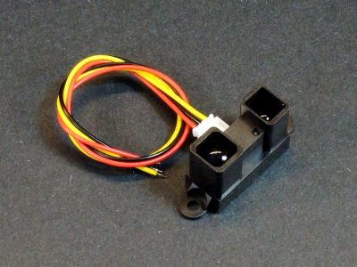
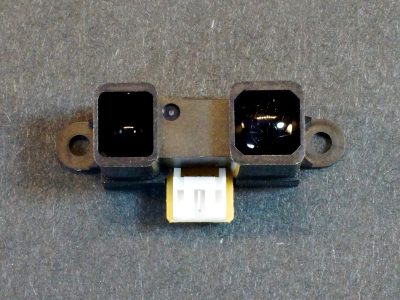
The IR Obstacle Avoidance Sensor Module uses an infrared emitter / receiver pair to detect obstacles in front of the sensor.
PACKAGE INCLUDES:
- IR Obstacle Avoidance Sensor Module
KEY FEATURES OF IR OBSTACLE AVOIDANCE SENSOR MODULE:
- Detection range from 2 cm to a maximum of 10 – 40 cm
- Uses HS0038B IR Receiver
- Oscillator frequency and duty cycle adjustment potentiometers
- 3.3 and 5V compatible
This IR Obstacle Avoidance Sensor uses an IR emitting LED and IR Receiver pair to detect obstacles in front of the sensor by the IR Receiver detecting the IR that is bounced of an object by the IR Emitter. Per specification, the device can detected objects in the range of 2 to 40 cm in front of it.
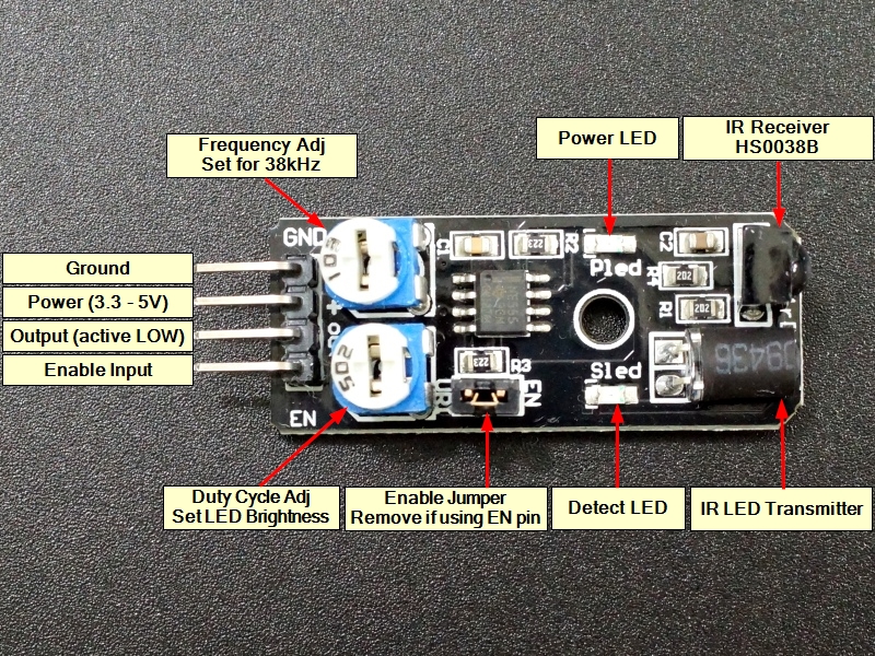
The clear LED is the IR emitter and the black device next to it is the HS0038B IR Receiver. The black case of the receiver helps to block light that is not in the IR spectrum. The device works by operating the IR LED at a frequency of 38KHz and detecting the IR energy from the LED which is bounced off an object and directed back at the IR Receiver module which is looking for an IR signal in the 38KHz frequency range.
The board includes two indicator LEDs. The PLED is illuminated when the board receives power. The SLED is illuminated momentarily when an obstacle is detected.
Module Adjustments
The module includes a 555 timer that is used to drive the IR LED. There are two single-turn potentiometers for adjusting the frequency and duty cycle of the 555 timer.
Frequency Adjust:
The module operates at 38 kHz as the HS0038B receiver module is designed to specifically look for IR pulsing at a 38 kHz rate. The potentiometer next to the GND pin is used to adjust the frequency of the 555 timer and is set to approximately 38 kHz from the factory and shouldn’t be readjusted unless you have a scope or frequency counter to calibrate the frequency. We have noted that some modules function best at a higher frequency up around 41kHz.
Duty Cycle Adjust:
The other potentiometer allows for adjustment of the duty cycle of the 555 timer. This affects the brightness of the IR LED and it can be fiddled with to try to change the distance at which objects are detected.
If this potentiometer is adjusted too far CW, the module may show that it is always detecting an obstacle even when it isn’t. In this case, adjust the potentiometer CCW until the LED goes off when there is no obstacle in front of the sensor.
Continuous / Pulse Mode Jumper:
There is a jumper on the assembly that when installed causes the 555 timer to operate continuously. This mode is most useful for basic testing of the module without requiring it to be hooked to a MCU.
If the jumper is removed, the EN pin on the 4-pin header is then used to enable the 555 timer to operate. This is the more typical way to use this module if using it in an actual application. The reason is the HS0038B receiver module is designed to filter out any IR signals that it sees continually, so it is better to pulse the IR.
Module Connections
There is a 4-pin header on the assembly for making connections.
1×4 Header
- GND = Ground. Must be common with the MCU ground.
- + = Power (3.3 – 5V)
- OUT = Output, normally HIGH. Output is pulsed LOW when an obstacle is detected.
- EN = Enable, active HIGH. When the on-board jumper is installed, EN is pulled to Vcc and always enabled. If jumper is removed, an output pin from a MCU can be used to enable the device.
OUR EVALUATION RESULTS:
This is a commonly used module for basic obstacle detection such as used on entry level robotic vehicles.
In our experience, these devices vary quite a bit as to the distance that objects can be detected both due to the way the devices are used as well as variances in the devices themselves. Some seem to max out at around 10cm while others will go up to 40cm or further. Making sure the IR emitter and receiver are pointed straight forward can help maximize the distance. They sometimes get tweeked around during shipping and handling.
If you are looking for a more capable obstacle avoidance sensor, we have a number available some of which are listed below including both IR and Ultrasonic types.
As shipped, the module has a jumper installed which causes the oscillator to run continuously. The basic functionality can be easily tested in this mode by applying ground and 3.3V or 5V to the ground and power pins and then temporarily inserting and removing an object from in front of the IR LED/Detector pair. The detection LED will blink when it detects an obstacle. IR reflectivity of the object will have an effect on the distance that it will be detected at.
In most cases, it is beneficial to shield the IR Transmitter LED from the receiver to prevent accidental direct coupling by using a short section of heat shrink or other tubing. We add this if it is not already present on the module
Note: If you found this page because you bought this module elsewhere and it is not working correctly, it is not uncommon for the C1 and C2 capacitors to be swapped. C2 near the IR Receiver should be a fairly thick capacitor and C1 near the IC should be much thinner as can be seen in the pictures.
The device is based on the HS0038B IR receiver which is an older part. One example of the datasheet can be found here. As can be seen from the datasheet, the IR detector is designed to reject signals that it sees continually as noise, so the IR detector is primarily designed to operate in a burst mode where the oscillator is enabled via the EN pin before the detector output is checked for an obstacle and it is then disabled again.
An example program that operates the device in this burst mode is shown below. It uses pins 8 & 9 for connecting to the module, but these can be any 2 digital pins.
For this software to work, be sure to remove the jumper from the board.
IR Obstacle Avoidance Module Example Program
/*
Exercise IR Obstacle Avoidance Sensor

Basic code to implement obstacle detection using the EN pin to enable the device.
When the EN pin is enabled, it will cause a false detect trigger, so it is necessary to enable
and then delay reading the detection output pin.  This also includes a 2nd read to make sure any
detection is valid.
If an obstacle is detected, you would obviously want to implement some type of
avoidance rather than simply loop as we do here.
*/

int LEDPin = 13;      // On board LED
int EnablePin = 8;   // Arbitrary digital pins that are connected to device.
int OutputPin = 9;

boolean objectDetect = false;
//===============================================================================
//  Initialization
//===============================================================================
void setup() {
  pinMode(LEDPin, OUTPUT);      // LED
  pinMode (EnablePin, OUTPUT);  // Enable Pin of the device
  pinMode (OutputPin, INPUT);   // Output Pin of the device

  Serial.begin(9600);
}
//===============================================================================
//  Main
//===============================================================================
void loop() {
 digitalWrite( EnablePin, HIGH);      // Enable the internal 38kHz signal from the 555 timer.
 delay(1);                            // Wait 1mSec for signal to stabilize
 if( digitalRead( OutputPin))         // If detector Output is HIGH,
 {
    objectDetect = false;             // then no object was detected;
 }
 else                                 // If the Output is LOW,
 {
    delay(1);                         // wait for another 1mSec and check again
    if( digitalRead(OutputPin))       // If the Output is now HIGH,
    {                                 // then first Read was noise
        objectDetect = false;         // and no object was detected, so ignore
    }
    else                              // else if the Output is still LOW,
    {
        objectDetect = true;          // then a valid object was detected.
        digitalWrite (LEDPin, HIGH);  // turn on LED to show the detection.
        Serial.println("Object Detected");  // Also send detection to the serial monitor window
        delay(500);
        digitalWrite (LEDPin, LOW);  // turn LED back off
    }
 }
  digitalWrite( EnablePin, LOW);      // Disable the internal 38kHz signal.
  delay(1000);                        // wait for 1 Sec or some other arbitrary time period
                                      //and then do again.
}
The board has a single hole in the middle that can be used for mounting.
BEFORE THEY ARE SHIPPED, THESE MODULES ARE:
- Inspected
- Heat shrink added to IR LED if not present
- Basic obstacle detection output verified
- Packaged in a high quality resealable ESD bag for protection and easy storage.
Notes:
- None
Technical Specifications
| Maximum Ratings | ||
| Vcc | Range | 3.3 to 5.5V |
| IMax | Maximum Current Draw | <5mA |
| Operating Ratings | ||
| Frequency | Detector Center Frequency | 38KHz |
| Detection Distance | 2 – 40cm | |
| Dimensions | L x W (PCB) | 45 x 17mm (1.77 x 0.67″) |
| Country of Origin | China | |
| Datasheet | HS0038B |

