Heartbeat Sensor Module
$1.09
Detects changes in infrared light shining through a fingertip.
6 in stock
Description
The Heartbeat Sensor Module is used to experiment with detecting the heart rate of an individual by detecting changes in infrared light shining through a fingertip.
PACKAGE INCLUDES:
- Heartbeat Sensor Module
KEY FEATURES OF HEARTBEAT SENSOR MODULE:
- Infrared (IR) transmitter
- Infrared receiver
- 3.3 or 5V operation
Operational Theory
These sensor modules can be used to try to detect the heart rate of an individual. It accomplishes this by shining an IR emitting LED on one side of a finger tip and detecting small changes in the received IR on the other side of the finger using a phototransistor. The fluctuations in the transmitted IR is caused by the blood being pumped through the finger. Commercial devices as used in doctor offices work on this same basic principal but obviously have a lot better capability.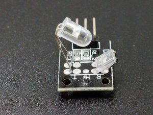
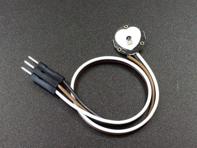
The module ships with the IR transmitter and receiver folded down to avoid damage. These element should be carefully unfolded and placed in position so that the transmitter and receiver point at each other with a snug fit on a fingertip.
The module is straight forward to operate. Hook up ground and Vcc (3.3 or 5V to match the MCU) and monitor the analog output using an analog input on an MCU. A fingertip is then placed between the IR emitter and the detector and software running on the MCU filters out the electrical noise, parses the data and spits out the heart rate (at least that is the theory!).
Module Connections
There is a 3-pin header on the assembly. Conveniently, the pins are marked on the back-side. With the connector facing to the left, the top ‘S’ pin is the analog output, center pin is Vcc (3.3 or 5V) and the bottom ‘-‘ pin is ground.
1 x 3 Header
- S = Analog output, connects to analog input on uC
- Center pin = Vcc (3.3 – 5V)
- ‘-‘ = Ground
OUR EVALUATION RESULTS:
These modules are interesting in concept, but can be very difficult to get meaningful information out of and so are recommended for more advanced hobbyists or those that just enjoy a good challenge. Let’s just say that if you find yourself in an ER, you don’t want to look down and see one of these clamped to your finger.
The reason is that the analog output of the device tends to be swamped with 60Hz noise from the home electrical system and the amount of change due to the heartbeat can be difficult to detect with all the ambient noise. Here are some things that can be done to improve your odds of getting a reasonable reading.
- As-shipped, the emitter LED and receiver are usually folded down for safe shipping. The emitter LED needs to point at the receiver, so carefully bend the LED up and the receiver out so that the two are facing each other more or less with enough room to place the tip of a finger between them. When running the setup with no finger in place, a lower number is better when when aligning the emitter/receiver pair. One of the pics shows the basic alignment that you are looking for.
- Shield the sensor assembly from stray light as much as possible while taking measurements. Turning lights off help to reduce the 60Hz flicker noise that can couple into the sensor.
- If there is a question as to whether the IR LED is working, a cell phone camera will typically pick up the blue glow form the IR LED if it is operating.
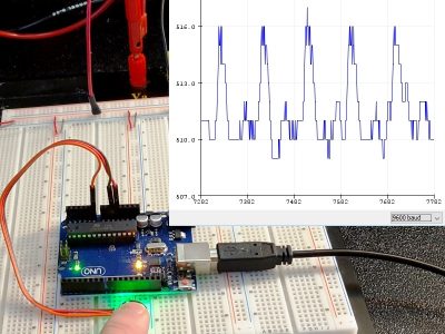
Here is a scope capture of the module output in our setup. The peaks within the electrical noise are the result of the heart rate being detected. In this case, it is a little less than 60 beats per minute. The challenge is to average the analog data to filter out the noise while detecting the peaks.
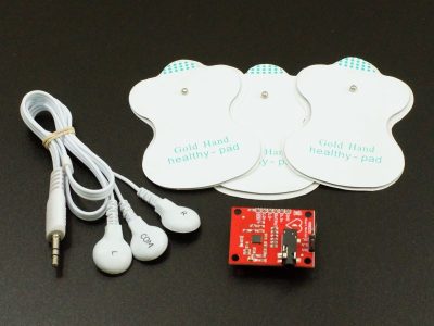
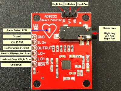
A good hardware project would be to add some noise filter and amplification to cleanup this signal and make it more usable. If you are looking for a more complete solution, checkout the PulseSensor down below that includes this type of noise filter and amplification as part of the module.
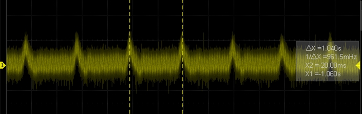
Scope capture of module output showing a heart rate of about 60 Beats Per Minute superimposed over the electrical noise
The simple program below can be used to monitor the analog output of the device to see how it basically reacts when a finger is inserted and to verify the output is good, but it makes no attempt to calculate the heart rate from the data. Samples are taken 10 times a second but this is arbitrary.
To test the module, simply connect the sensor output to any analog input on the uC (we use A0 in the example below) and apply 5V and ground to the module – then insert finger.
Heartbeat Sensor Module Test Program
/*
Heatbeat Detection Sensor Module test

Basic code reading the output of the module.
*/
int sensorPin = A0;  // Arbitrary analog pin to connect sensor output to
int period = 100; // Delay in milliseconds between readings

//===============================================================================
//  Initialization
//===============================================================================

void setup ()
{
  Serial.begin (9600); // the baud rate of the serial data
}
//===============================================================================
//  Main
//===============================================================================
void loop ()
{
    static double oldValue = 0; // used for averaging.

    int rawValue = analogRead (sensorPin); // Value read from the analog pin.  Will be between 0-1024
    Serial.println (rawValue);
    delay (period);
}
BEFORE THEY ARE SHIPPED, THESE MODULES ARE:
- Sample inspected and tested per incoming shipment
Notes:
- This module is the same or similar to the KY-039
Technical Specifications
| Maximum Ratings | ||
| Vcc | 3.3 – 5V | |
| IMax | Maximum Current Draw | < 12mA (measured) |
| Operating Ratings | ||
| Wavelength | 850-940nm (typical) | |
| Dimensions | L x W (PCB) | 20 x 15mm (0.75 x 0.60″) |