PulseSensor Heart Rate Sensor Module
$3.49
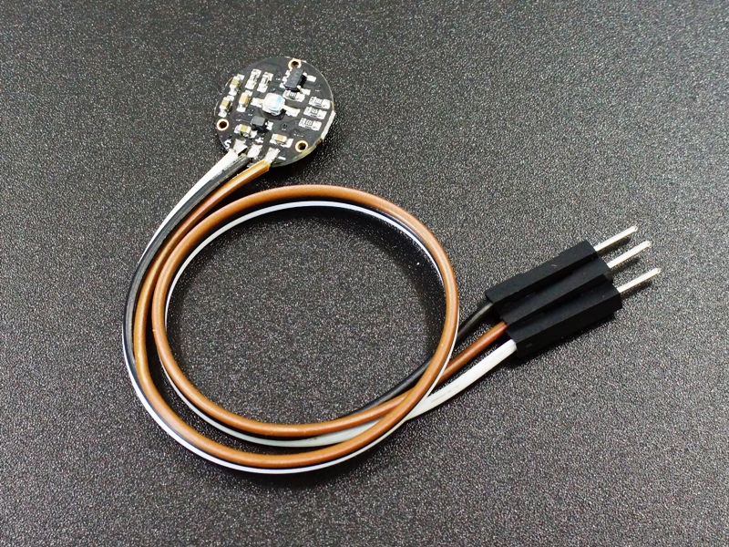
Easy to use finger-tip heart rate detector module with built-in noise filter and signal amplification.
16 in stock
Description
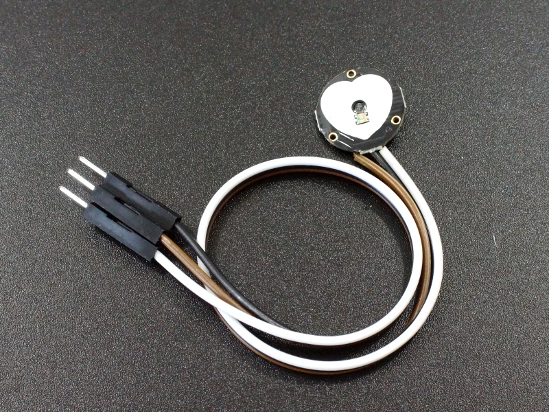
The PulseSensor Heart Rate Sensor is an easy to use finger-tip heart rate detector module with built-in noise filter and signal amplification.
PACKAGE INCLUDES:
- PulseSensor Heart Rate Sensor Module w/ breadboard leads
KEY FEATURES OF PULSESENSOR HEART RATE SENSOR MODULE:
- Small form factor
- Built-in noise filter and signal amplification for easier signal discrimination
- Handy breadboard leads and pins
- 3.3 or 5V operation
Operational Theory
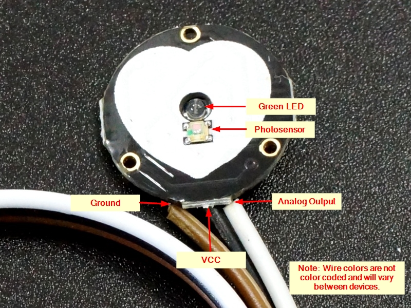
If you look closely at the module, you will see a small photosensor on the front side with the silk-screened heart where you place your finger.
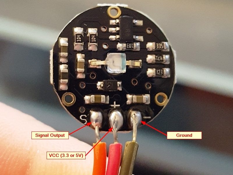
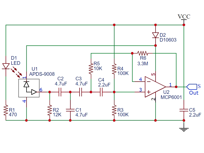
On the backside of the module you will find the rest of the components including a reverse mounted green LED that shines through the hole, an Op Amp and a number of resistors and capacitors and a diode.
The sensor works by shining a bright green LED into a finger (or other body part like an ear lobe) and detecting the amount of light that is reflected back used a photosensor that is tuned to the green light spectrum.
As blood is pumped through the finger with each heartbeat, the amount of reflected light changes, creating a changing waveform on the output of the photosensor that is representative of the heart rate.
This signal from the photosensor is small and riding on a changing DC bias, so the signal is then passed through an R/C filter network and then amplified using an Op Amp to create a signal that is much larger, cleaner and easier to detect using an analog port on an MCU.
Module Connections
The wire colors are not color coded, so ensure that you look at the markings on the back of the module to ensure that you have the three wires correctly identified
The module can be powered from 3.3 or 5V. The positive voltage connects to ‘+’ and ground connects to ‘-‘. There is a reverse protection diode on the module to prevent damage should the power leads be accidentally reversed.
The 3rd ‘S’ wire is the analog signal output from the sensor and this will connect to the analog input of a uC.
1 x 3 Wire Harness
- ‘S’ = Signal output connects to uC analog input
- ‘+’ = Vcc connects to 3.3 or 5V
- ‘-‘ = Ground connects to uC ground
Practical Use Considerations
This device is a small unprotected circuit board which works fine for bench top testing and experimenting with heart rate detection. If you intend instead to use it for a more real-world application such as making a heart rate monitor to use while you are riding an exercise bike, you should plan to provide some protection to the module from salty sweat which can corrode and short circuit the circuitry as well as strain relieve the wires to prevent them from breaking from being constantly flexed.
Since the sensor comes with short breadboard style wires, you may need to replace them with longer wires that are more suitable for you application. You will want to do this before you seal the back of the unit as noted below.
The back of the module can be protected using hot melt glue. To apply, simply apply a glob of hot melt glue on something like blue painters tape and then press the back of the module into the hot glue. The hot melt glue also helps to strain relieve the wires if some is also dabbed on the front side of the wires as well. Once cool, remove from the tape and trim the excess glue from around the edges using nail trimmers or a similar tool.
The nice thing about hot melt is that it can be removed if you decide to make changes, but more permanent sealers like epoxy or RTV can also be used. Just be sure to use non-corrosive types that are compatible with electronics.
The front of the module can be protected using a transparent self adhesive vinyl sticker or similar. You should check performance before and after applying any protective layer over the LED and sensor to make sure the performance is not too greatly affected.
OUR EVALUATION RESULTS:
While the device is not quite hospital grade, it does a respectable job and is a big improvement over using the simple modules that include just an LED and photosensor.
The PulseSensor is an open source device originally created by PulseSensor.com. There is a wealth of information available on their website. If you download the PulseSensor Playground library in the Arduino IDE, it will also install a number of sample programs that can be used with the sensor.
The simple program below reads the sensor and blinks the on-board LED each time it detects a pulse. It does not require an library, it simply reads the output of the sensor directly and blinks the LED if the reading is above or below a threshold value.
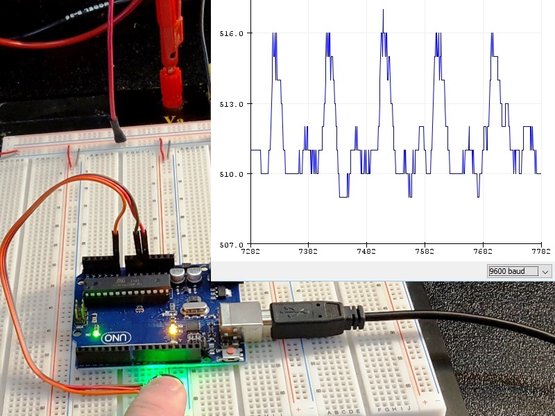
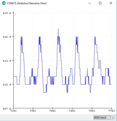
More interestingly, you can open the Serial Plotter window which will plot the output of the sensor so that you can see how the position of the finger and pressure affects the reading.
To get it running, simply hook the sensor up to 5V and ground and connect the Signal pin to A0. Place your finger on the sensor and give it a few moments for the plotter window to autoscale and basically zoom in on signal. You will find that finger position and amount of pressure will have a significant affect on the reading. Generally you want just a light pressure on the sensor.
An example Serial Plotter window output reading is shown here to the right. In this case, the pulse is registering between about 510 and 516. If you are powering the sensor off of 5V, the default threshold setting of 512 will get you close but you may want to play with that value for best detection. You can look at the Y-Axis of the serial plotter graph to see the range of numbers that the sensor is providing and adjust the threshold value based on that to give the best pulse detection.
If you wanted to determine the pulse rate, you could count the milliseconds between the detected pulses and calculate it from the formula Pulse Rate = 60 / (milliseconds/1000)
PulseSensor Heart Rate Test Program
/*  PulseSensor Heart Rate Test Program
 *  Basic code to evaluate the PulseSensor heart rate sensor module
 *  Connect to 5V, Gnd and Signal goes to A0
 *
 *  When heartbeat detected, flash on-board LED
 *  Open Serial Plotter window to observe the detected waveform.
 *  Threshold value can be adjusted for best detection.
*/
int const PULSE_SENSOR_PIN = 0;   // 'S' Signal pin connected to A0

int Signal;                // Incoming ADC data. Value can range from 0-1024
int Threshold = 512;       // Sets ADC threshold for what constitutes a heartbeat.

//===============================================================================
//  Initialization
//===============================================================================
void setup() {
   pinMode(LED_BUILTIN,OUTPUT);  // Built-in LED will blink to your heartbeat
   Serial.begin(9600);          // Set comm speed for serial plotter window
}

//===============================================================================
//  Main
//===============================================================================
void loop() {

  Signal = analogRead(PULSE_SENSOR_PIN); // Read the sensor value

  Serial.println(Signal);                // Send the Signal value to Serial Plotter

   if(Signal > Threshold){               // If the signal is above threshold,turn on LED
     digitalWrite(LED_BUILTIN,HIGH);
   } else {
     digitalWrite(LED_BUILTIN,LOW);            // Else, if signal below threshold, so turn off LED
   }
delay(10);
}
BEFORE THEY ARE SHIPPED, THESE MODULES ARE:
- Sample inspected and tested per incoming shipment.
Notes:
- None
Technical Specifications
| Maximum Ratings | ||
| Vcc | 3.0 – 5.5V | |
| IMax | Maximum Current Draw | < 4mA |
| VOut | Output Voltage Range | 0.3V to Vcc |
| Wavelength | LED Output | 565nm |
| Sensor Input | 525nm | |
| Dimensions | L x W (PCB) | 15.8mm (0.625″) |
| Lead Length | 20cm (7.8″) | |
| Datasheets | Reverse Mount LED | Kingbright AM2520ZGC09 |
| Photosensor | Avago APDS-9008 | |
| Op Amp | Microchip MCP6001 |

