G3MB-202P Solid State Relay 2A
$1.69
5V logic compatible SSR controls 100-240VAC@2A
4 in stock
Description
5V logic compatible solid state relay can control up to 100-240VAC@ up to 2A
PACKAGE INCLUDES:
- G3MB-202P Solid State Relay
KEY FEATURES OF G3MB-202P SOLID STATE RELAY:
- Phototriac coupler input isolation
- Switch 100-240VAC @ 2A
- Built-in snubber circuit
- Zero cross control
- Active HIGH control input
- 5V logic compatible
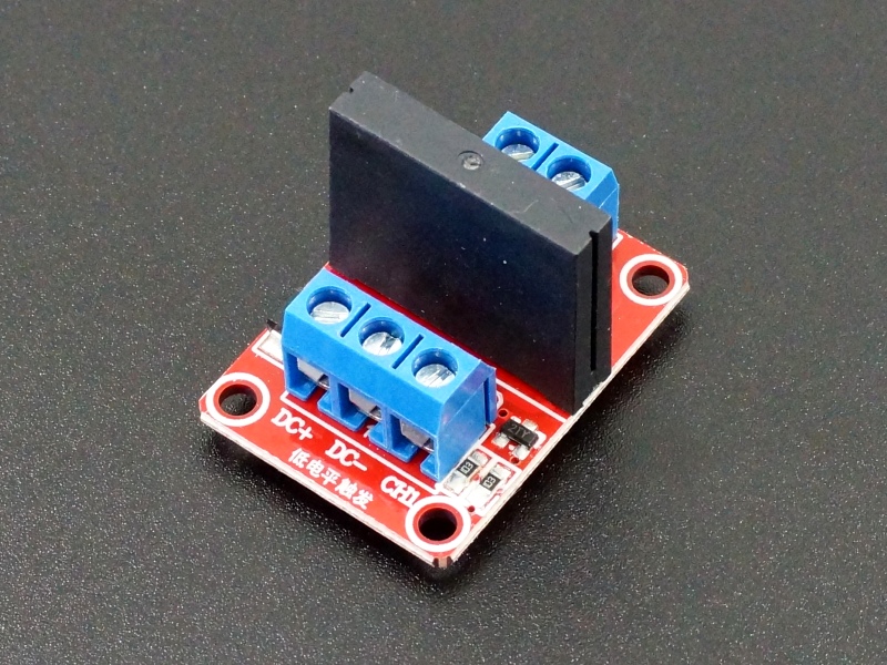
Solid State Relays (SSRs) are handy for controlling smaller AC loads. These SSRs are obsoleted by the Mfr, but they are the SSRs used in most of the solid state relay modules out of China. They are offered as replacement parts or can be used to home brew a setup.
This SSR switches one channel of 100-240VAC at up to 2A. The SSR can turn switch AC ON or OFF, but it cannot be used for dimming. it also cannot be used to switch DC voltages.
Compared to a standard electro-mechanical relay, the SSR switches quicker and does not have the long-term mechanical reliability concerns of a mechanical relay as long as the maximum current limits are observed. The main downside is that it cannot be used to control DC power and max current is limited to 2A.
Note that unlike mechanical relays, SSRs cannot be operated in parallel to increase their current handling capability. This is because the SSRs will not turn on at exactly the same time and the first one to turn on will carry the full load until it fails or the fuse blows and then the second one will turn on and also subsequently fail.
For redundancy purposes, it is possible to operate 2 is parallel if the load is within the 2A limit of a single SSR. If the SSR carrying the load fails, the other SSR will automatically switch on.
SSR Control
These SSRs are 5V logic compatible.
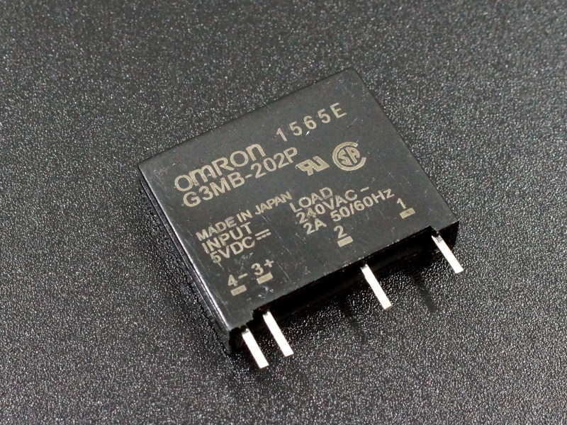
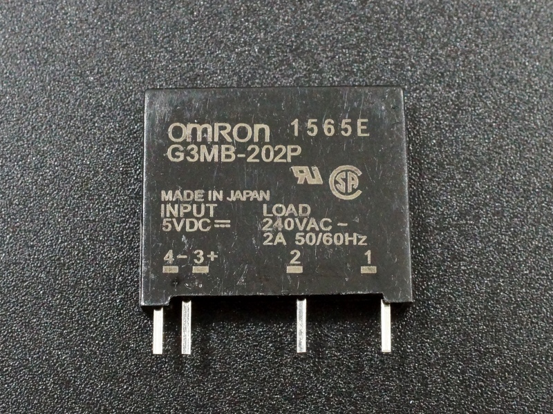
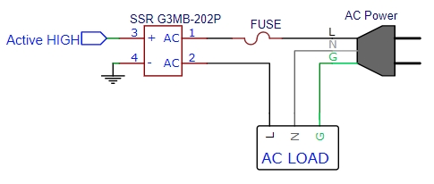
- Pin 4 (-) Connects to ground.
- Pin 3(+) Connects to logic control signal from MCU. When turned on, the SSR draws about 12mA from the control pin.
Opto-Isolation
The SSR has built-in phototriac coupler on its logic control input.
These phototriac couplers provide electrical isolation between the logic control input and the SSR power output as an added layer of protection in case of a major failure on the AC load of the SSR. An external optocoupler is not needed.
SSR Operation
The output of the SSR is rated to switch AC power over a maximum range of 75-264VAC at 2A and recommended range of 100-240VAC.
Output can be thought of as SPST type and is NO (Normally Open). A logic HIGH energizes the SSR, so the two output terminals are connected and power passes through the relay. A logic LOW (or no connection) de-energizes the SSR and the output terminals are open.
The SSR operates at the zero cross point of the AC waveform so can switch as fast as every half cycle or 8.3mS.
The drawing below shows the typical circuit connections.
When switching AC power, proper safety should be observed to ensure the wiring is secure, connections are insulated or not easily contacted to avoid an electrical shock.
FURTHER READING:
Notes:
- None
TECHNICAL SPECIFICATIONS
| Logic Input | Voltage range | 4-6VDC (5V typical) |
| Logic High | ≥ 4V | |
| Logic Low | ≤ 1.0V | |
| Drive Current | < 14mA | |
| Relay Rating | Maximum | 75-264VAC @ (0.1 – 2A) |
| Recommended | 100-240VAC @ (0.1 – 2A) | |
| Max Inrush Current | 30A (8.3mS) | |
| Relay Type | Omron | G3MB-202P |
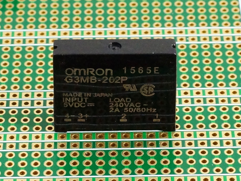
| Dimensions | L x W x H | 24.5 x 20.5 x 5.5mm (0.96 x 0.81 x 0.22″) |

