Optical Endstop Module
$2.95 Original price was: $2.95.$1.95Current price is: $1.95.
Designed for use as an endstop for 3D printers but it can be used for other IR beam interrupter purposes as well.
Out of stock
Description
This infrared sensor is designed for use as an endstop for 3D printers but it can be used for other IR beam interrupter purposes as well.
PACKAGE INCLUDES:
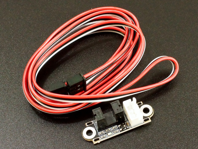
- Optical Endstop Module
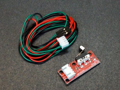
- 100 cm cable
KEY FEATURES OF OPTICAL ENDSTOP MODULE:
- Detects presence of an object that passes through the uprights.
- Use as travel limit switch on 3D printers or other beam break detect applications
- 100 cm long 24AWG cable
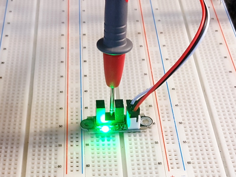
- Green LED Lights when beam is broken
- 3.3 and 5V logic compatible
The module was designed to detect travel limits for 3D printers, but they will work for many beam-break applications such for a security system or counting revolutions of a spoked wheel that passes through the uprights.
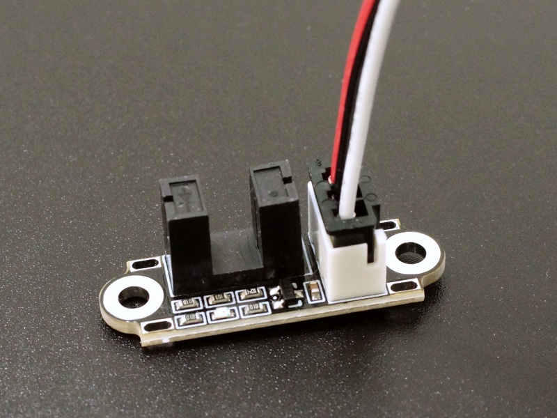
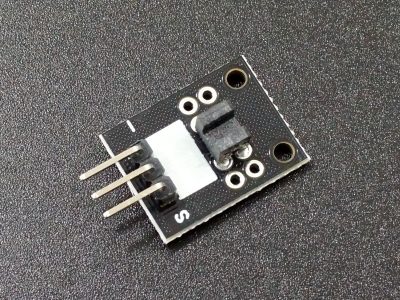
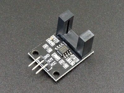
This module has an IR transmitter and receiver pair that face each other across a U-shaped housing. An object moving through the uprights breaks the IR beam.
The output is normally held LOW. When the beam is broken, the output goes HIGH and a green LED on the module illuminates.
The module uses a 3-pin 2.54mm JST style connector. The other end of the cable terminates in the same kind of connector and is compatible with a standard 2.54mm male headers..
Module Connections
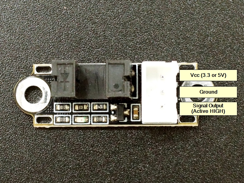
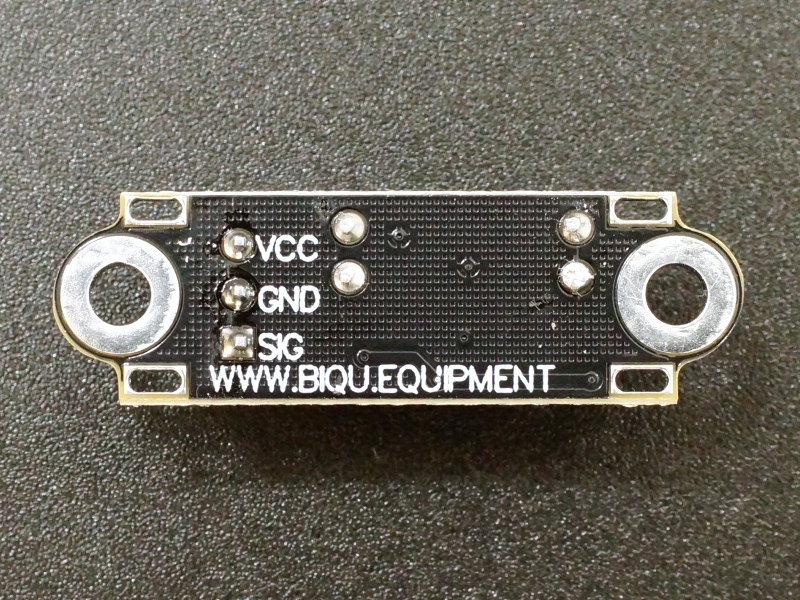
Note that the cable is not color coded. Red does not necessarily go to Vcc, so be sure to follow the pin-out of the connector labeled on the back of the board as shown below
1×3 Connector
- VCC= 3.3 or 5V to match the MCU.
- GND = Ground which should be common with the MCU.
- SIG = Signal output of the module. This pin is normally LOW. When the IR beam is broken, the output goes HIGH (Vcc).
The module has 2 large mounting holes.
OUR EVALUATION RESULTS:
Build quality is good on these modules but there are a couple of things to note to make sure it is right for your application.
- The sensor output is analog rather than having a comparator digital output. This means that if an object is moving slowly through the uprights, while the beam is partially blocked it can result in an output voltage that is in-between the valid logic states of HIGH or LOW for a period of time.
- Similarly if the object moving through the uprights is semi-transparent to IR, the output will go to a level that is somewhere in-between ground and Vcc.
- The cable exits on the same side as the sensor. This can be good or bad depending on your application and how the sensor is to be mounted.
BEFORE THEY ARE SHIPPED, THESE MODULES ARE:
- Sample inspected per incoming shipment
Notes:
- None
Technical Specifications
| Operating Ratings | Vcc Range | 3.3 – 5VDC |
| Logic high | Pulled to Vcc via transistor | |
| Logic Low | Pulled to Ground | |
| Dimensions | L x W (PCB) | 35mm x 11.5mm (1.4 x 0.45″) |
| Height U-Channel | 10.5mm (0.41″) | |
| H x W (Inside U-Channel) | 8 x 5mm (0.32 x 0.2″) | |
| Depth of intrusion into U-Channel to interrupt beam | 3.5mm (0.14″) | |
| Cable Length | 100cm (39″) | |
| Wire Gauge | 24AWG | |
| Country of Origin | China |

