Due R3 (Arduino Compatible)
$42.95
Arduino compatible board with 32-bit 84MHz ARM processor operating at 3.3V.
10 in stock
Description
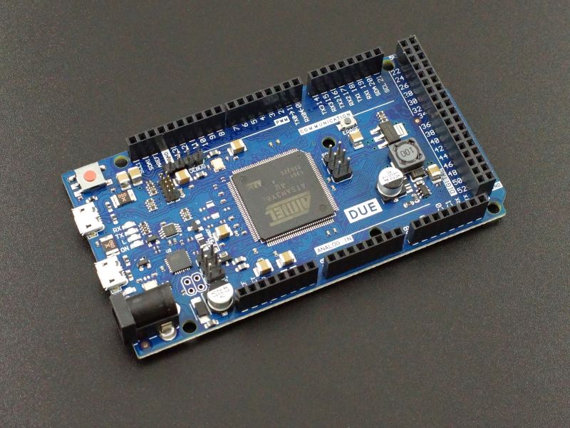
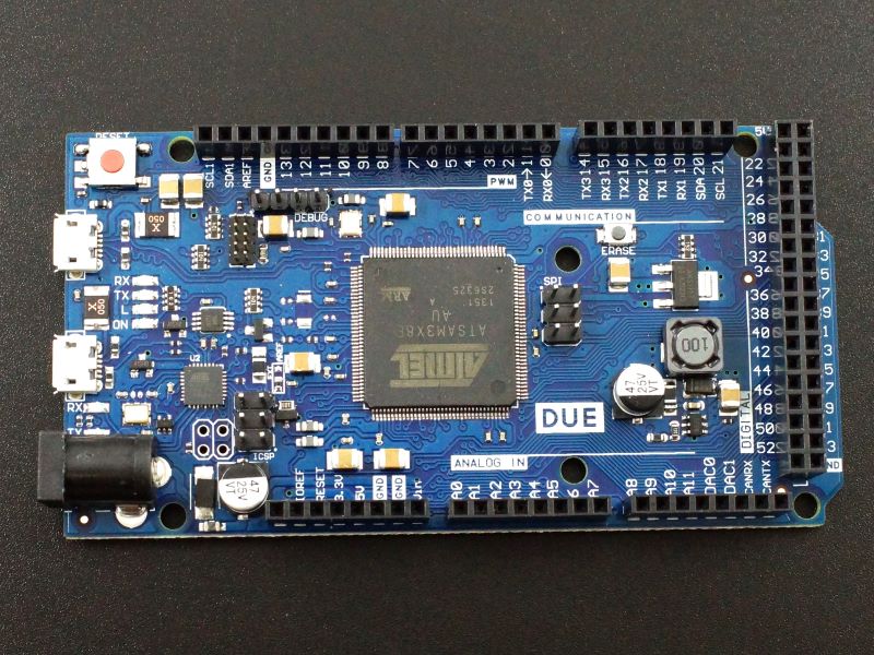
The Due R3 is a powerful Arduino compatible board based on a 32-bit ARM processor running at 84MHz and operating at 3.3V. It is perfect for more demanding applications that require high processing performance and a lot of I/O.
Package Includes:
- Due R3 (Arduino Due R3 compatible)
Key Features of DUE R3:
- AT91SAM3X8E ARM Cortex-M3 running at 84MHz
- ATmega16U2 programmed as a serial to USB converter
- 2 USB ports – Native and Programming. USB OTG capable
- 512KB Flash memory
- 54 Digital I/O all with interrupt capability. Digital I/O can be expanded up to 72
- 12 PWM shared with the digital I/O. Up to 12-bit resolution
- 12 Analog inputs with 12-bit resolution that can also be used as digital I/O
- 2 Analog DAC outputs with 12-bit resolution
- 4 Hardware serial ports
- 2 I2C Ports
- Includes ERASE_CMD resistor mode
- 3.3V Operation
The Due R3 is the same form factor as the Mega 2560 but has a more powerful processor with more memory and operates at 3.3V instead of the more typical 5V of other Arduino boards.
If you need high performance and a lot if I/O, it is a good choice for more advanced projects. As an example, the MCU is fast enough to synthesis music using the 2 DAC outputs.
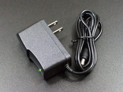
The Due R3 operates at 3.3V which is regulated on-board and can be supplied via an external power supply or through the USB port connection. The power source is selected automatically if both are available. If an external supply is used, it is recommended to use a supply between 7-12V. Our 7.5V AC adapter works well for powering these boards.
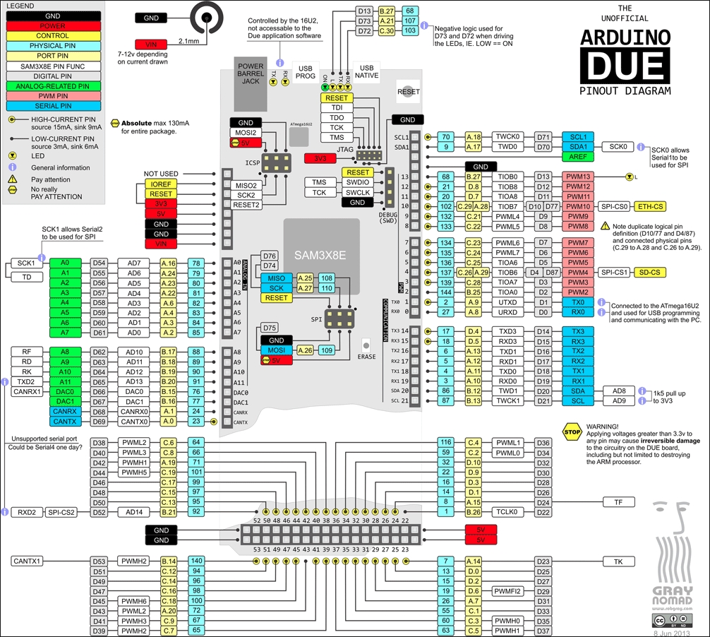
The attached Due R3 board pin-out by Rob Gray shows the functions for the pins. Note that most pins provide multiple functionalities. Also note that the pins have a little less drive capability than the standard AVR based Arduino boards. Most can source 15mA and sink 9mA, but some are limited to sourcing 3mA and sinking 6mA. These are shown on the pinout.
The board is compatible with shields that support 3.3V and are compliant with the 1.0 Arduino pinout.
There is a built-in CAN bus (CANRX / CANTX) which can be accessed via the Due_Can library in the IDE.
The built-in 12-bit DAC outputs are a nice feature that is not found on other Arduino boards.
Programming the Due
Programming of the Due is a little different than standard Arduino boards, so there are a couple of things to pay attention to.
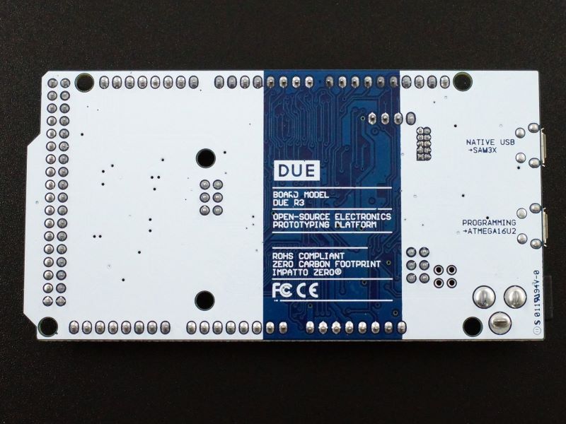
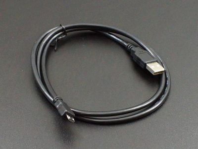
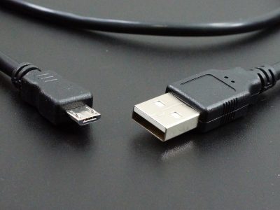
The board has two micro USB connectors which are labeled on the bottom side of the board.
The one nearest the power plug is referred to as the Programming Port and connects to the ATMega16U2 USB to serial converter chip as used on typical Arduino boards. This port should be used for any programming activities.
The other USB is called the Native USB Port that connects directly to the SAM3X MCU and can be used if the Due is being used as a client USB device (such as acting as a mouse or keyboard to a computer) or acting as a host for devices connected to the Due (like interfacing to a mouse or android phone)
The Due is not one of the default Arduino boards available in the IDE board selections. To install the Due device in the IDE, go to Boards Manager. Find and install the Arduino SAM Boards(32-bits ARM Cortex-M3). Once this is installed, two new Due Board options will become available. Select the Arduino Due (Programming Port) option.
The Due differs from other AVR based MCUs because the flash memory needs to be erased before being reprogrammed. This is normally handled automatically by the IDE as part of the programming sequence and you don’t need to worry about it. Should there be an issue like bricking the device with a bad download, it is possible to manually erase the flash by following these steps:
1. Press the on-board ‘ERASE’ button for 1 second
2. Press the UPLOAD button in the IDE
3. Press the on-board RESET button
If your board is not recognized by the OS or you run into any issues getting connected, check out the additional info in this link: https://www.arduino.cc/en/Guide/ArduinoDue
Our Evaluation Results:
These are nice Arduino compatible (clone) assemblies with good build quality.
The main thing to note and pay attention to is that the I/O operates at 3.3V and is not 5V tolerant. Level shifting may be required to interface to some 5V peripherals.
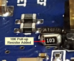
These boards are known to occasionally exhibit a power on issue where the program is not automatically run at power up until a board reset is executed. We upgrade the boards by adding a 10K pull-up resistor to the ERASE_CMD line which solves this issue as shown to the right.
This improvement was added to the latest Arduino brand R3-E revision boards, but clone boards are always missing this part as they are based on the previous rev. If you have a clone Due R3 from another source and having issues with the program not running at power-up, this is most likely your issue.
The micro USB connector has a very small footprint and solder pads which makes it popular for small MCUs or where space is limited. As with any MCU that uses the micro USB connector, some care should be taken not to put excessive upwards strain on the USB cable or it is possible for the connector to be dislodged from the board. Mainly ensure that you push the cable straight in or pull straight out and don’t pry it up in the process.
The Arduino Due Forum linked below is a good source of information on using the more advanced features of this board.
Before they are shipped, these modules are:
- Inspected
- 10K resistor added to ERASE_CMD line
- Powered up and the example program ‘Blinky’ which blinks the on-board LED once per second is downloaded to verify basic operation.
- Repackaged in resealable ESD bag for safe storage.
Further Reading:
Additional Due Info on Arduino.cc website
Notes:
- None
Technical Specifications
| Microcontroller | AT91SAM3X8E | |
| Clock Speed | 84MHz | |
| Serial to USB Converter | ATmega16U2 | |
| Operating Voltage | 3.3V | |
| Input Voltage (recommended) | 7-12V | |
| Digital I/O Pins | 54 (expandable to 72) | |
| PWM I/O Pins (Shared with Digital I/O) | 12 (up to 12-bit resolution) | |
| Analog Input Pins (can also be used as digital I/O) | 12 (12-bit resolution) | |
| Analog Output Pins (can also be used as digital I/O) | 2 (12-bit resolution) | |
| DC Current per I/O Pin | Up to 15mA Sourcing, 9mA Sinking | |
| Flash Memory | 512 KBytes | |
| SRAM | 96 KBytes | |
| Built-in LED | Attached to digital I/O Pin 13 | |
| USB Connector Style | Micro-B Type Female (x2) | |
| Board Dimensions (PCB) | 102 x 53.4mm (4 x 2.1″) | |
| Country of Origin | China |

