Digital Thermistor Temperature Sensor Module
$1.39
NTC thermistor with analog output and adjustable digital output.
6 in stock
Description
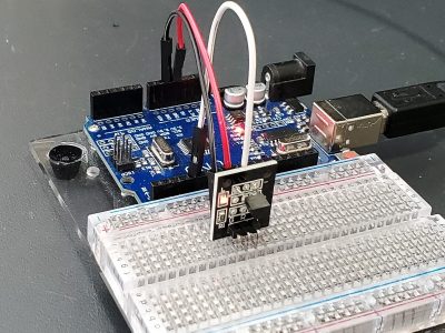
The Digital Thermistor Temperature Sensor Module uses an NTC thermistor to measure temperature and provides both digital and analog outputs.
PACKAGE INCLUDES:
- Digital Thermistor Temperature Sensor Module
KEY FEATURES OF DIGITAL THERMISTOR TEMPERATURE SENSOR MODULE:
- Uses NTC thermistor
- Measurement range of -55 to +125°C
- Provides analog output of reading
- Provides digital output with adjustable temperature set-point
- 3.3 and 5V operation
The module uses an NTC thermistor to measure temperature and provides both analog and digital outputs.
Thermistors are essentially resistors whose resistance value changes with changes in temperature. NTC stands for ‘Negative Temperature Coefficient which means that the sensor resistance will decrease as temperature increases.
The thermistor is in series with an 10K resistor which creates a voltage divider. As the thermistor warms up, the resistance lowers and the analog output either increases towards Vcc or decreases toward ground depending on the module construction.
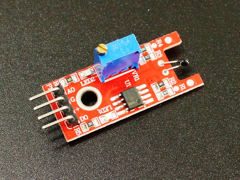
There is a red LED1 that is lit whenever power is applied to the module.
Outputs
The analog (A0) output is the raw analog voltage output from the thermistor. This is normally input into an analog port on an MCU where it can be read and the temperature can be calculated.
The digital (D0) output is normally LOW and goes HIGH when a temperature threshold has been reached. When the output goes HIGH, LED2 lights. The set-point for the temperature threshold can be adjusted using the potentiometer on the module. Turning the adjustment CCW increases the temperature set-point. This output is normally connected to a digital input on an MCU or could directly control a relay or similar device once the temperature threshold has been reached.
Module Connections
There is a 4-pin header on the assembly.
1 x 4 Header
- A0 = Analog output, connects to analog input on MCU
- GND / G = Ground
- ‘+’ = Vcc (3.3 or 5V)
- D0 = Digital output, connects to digital input on MCU
OUR EVALUATION RESULTS:
These modules are interesting for experimenting with thermistors.
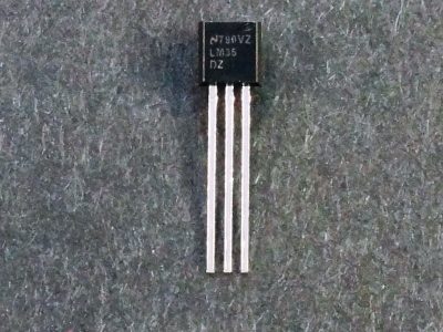
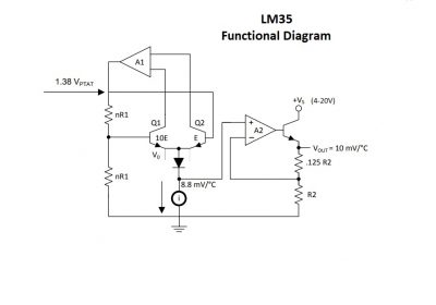
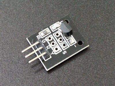
Thermistors do require post processing to convert their output to temperature and are not as easy to use as sensors that output directly in temperature such as the LM35 or DS18B20. If your goal is simply to get accurate temperature readings, I would recommend sticking with one of those sensors, some of which are available below.
The simple program below monitors both the analog and digital outputs of the device and prints the results on the Serial Monitor window. If you are looking for a program that converts the analog output to a temperature, you can find one here.
Digital Thermistor Temperature Sensor Module Example Program
/*
Digital Thermistor temp Sensor module test

Basic code for reading the outputs of the thermistor module.
*/
int analogPin = A0;  // Any analog pin on Arduino
int digitalPin = 3;  // Any digital pin on Arduino
int adcSample = 0;   // Variables to hold values
int digitalSample = 0;
//===============================================================================
//  Initialization
//===============================================================================
void setup()
{
  Serial.begin(9600);  // Set comm speed for debug window messages
}
//===============================================================================
//  Main
//===============================================================================
void loop()
{
  adcSample = analogRead(analogPin);        // read analog value from pin and store
  digitalSample = digitalRead(digitalPin);  // read digital value from pin and store
  Serial.print("Analog Output: ");
  Serial.println(adcSample);
  Serial.print("Digital Output: ");
  Serial.println(digitalSample);
  delay(3000);
}
BEFORE THEY ARE SHIPPED, THESE MODULES ARE:
- Inspected
- Basic outputs verified
- Packaged in a resealable ESD bag for protection and easy storage.
Notes:
- This module is the same or similar to the KY-028
Technical Specifications
| Maximum Ratings | ||
| Vcc | 3.3 – 5V | |
| IMax | Maximum Current Draw | < 7mA |
| Operating Ratings | ||
| Temperature Range | -55 to +125°C (+/- 0.5°C) | |
| Dimensions | L x W (PCB) | 36 x 15mm (1.4 x 0.6″) |

