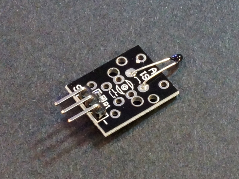
Thermistor Temperature Sensor Module
$0.95
Module uses an NTC thermistor to measure temperature and provide an analog output.
10 in stock
Description
The Thermistor Temperature Sensor Module uses and NTC thermistor to measure temperature and provides and analog output.
PACKAGE INCLUDES:
- Thermistor Temperature Sensor Module
KEY FEATURES OF THERMISTOR TEMPERATURE SENSOR MODULE:
- Uses NTC thermistor
- Measurement range of -55 to +125°C
- Provides analog output of the reading
- 3.3 and 5V operation
This module utilizes an NTC thermistor for measuring temperature. The output is normally input into an analog port on a uC where it can be read and the temperature calculated.
Thermistors are essentially resistors whose resistance value changes with changes in temperature. NTC stands for ‘Negative Temperature Coefficient which means that the sensor resistance will decrease as temperature increases.
The thermistor is in series with an 10K resistor which creates a voltage divider. As the thermistor warms up, the resistance lowers and the analog output increases towards Vcc.
The sensor is capable of reading temperature in the range of -55 to +125°C with an accuracy of +/- 0.5°C.
Module Connections
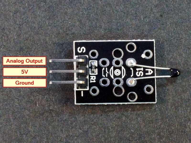
The module has a 3-pin header on the assembly for connections. The ‘-‘ pin is connected to GND, the center pin is connected to Vcc and the ‘S’ pin is connected to an analog input pin on the uC. If the output goes in the wrong direction i.e. resistance goes up as temperature goes up, reverse the power and ground pins.
1 x 3 Header
- ‘-‘ = Ground
- Center pin = 5V
- S = Signal Output. Connects to analog input pin on uC
OUR EVALUATION RESULTS:
This is a commonly used module for basic temperature measurement. Once up and running with a uC, it is easy to test the module by using the fingers to warm the sensor and monitor the output.
Using the device requires some math to convert from the voltage output to the temperature. In our own test code, we use the Beta method for temperature calculation, but there are several different formulas that can be used. The nice thing about the Beta method is that you can measure your component values and enter them into the fields if your sensor is constructed a little different.
The most difficult part is calculating the Beta value which is in the datasheet if you are using a fully spec’d part. If the part is unknown, as is the case with most of these types of modules, you can calculate it. This link is for a handy Beta Calculator where you measure the resistance of the thermistor at 2 different temperatures and it will give you the Beta value.
To use this program, you will need several values or measurements to plug into the program:
- Balance Resistor: Measure the actual value of the balance resistor that is on the module. It is nominally a 10K resistor, so use 10000.0 if you can’t measure it more accurately.
- Max ADC: Typically 1023.0 if using a standard 10-bit analog input.
- Beta: From the Beta Calculator as noted above. You will need to take a couple of temperature measurements to get this value.
- Room Temp: The current room temperature measured as accurately as you can. You will then need to use an on-line conversion tool to get the value in Kelvin.
- Resistor Room Temp: This is the resistance value of the NTC thermistor on the module measured at the room temperature you measure above. Be sure not to accidentally heat the thermistor with your fingers while taking the measurement.
We are bringing the sensor output into the A0 analog input pin, but this can be changed to any convenient analog input.
Thermistor Temperature Sensor Module Example Program
/*
NTC Thermistor module test

Basic code for reading the output of the thermistor module. It uses the Beta method of calculating
the temperature.  Beta # determined using on-line calculator and measuring 2 thermistor resistances
over different temps.
*/

const double BALANCE_RESISTOR   = 10010.0;  // Measured value of on-board divider resistor
const double MAX_ADC            = 1023.0;  // Max number of ADC steps (10-bit in this case)
const double BETA               = 4242.0;   // Beta value (from datasheet or calculated)
const double ROOM_TEMP          = 292.75;   // room ambient temperature in Kelvin
const double RESISTOR_ROOM_TEMP = 125000.0;  // Measured value of thermistor at room temp

double currentTemperature = 0;  // Variable to hold measured temperature

int thermistorPin = A0;  // ADC pin on Arduino (Mega2560 in this case)

//===============================================================================
//  Initialization
//===============================================================================
void setup()
{
  Serial.begin(9600);  // Set comm speed for debug window messages
}

//===============================================================================
//  Main
//===============================================================================
void loop()
{
  currentTemperature = readThermistor();

  Serial.print("Current Temp is ");
  Serial.print(currentTemperature);
  Serial.print("C  /  ");
  Serial.print(currentTemperature * 9 / 5 +32);
  Serial.println("F");

   delay(3000);
}

//===============================================================================
//  Functions
//===============================================================================

double readThermistor()
{
  // Local Variables
  double rThermistor = 0;            // Thermistor resistance value
  double tKelvin     = 0;            // Calculated temperature in Kelvin
  double tCelsius    = 0;            // Calculated temperature in celsius
  int    adcSample   = 0;            // ADC measurement

  adcSample = analogRead(thermistorPin);  // read from pin and store

  rThermistor = BALANCE_RESISTOR * ( (MAX_ADC / adcSample) - 1);

  tKelvin = (BETA * ROOM_TEMP) /
            (BETA + (ROOM_TEMP * log(rThermistor / RESISTOR_ROOM_TEMP)));

  tCelsius = tKelvin - 273.15;  // convert kelvin to celsius

  return tCelsius;    // Return the temperature in Celsius
}
Before they are shipped, these modules are:
- Inspected
- Basic analog temperature output verified
- Packaged in a resealable ESD bag for protection and easy storage.
Notes:
- If your readings are wonky, try reversing the 5V and ground connections.
- This module is similar to or the same as the KY-013.
Technical Specifications
| Maximum Ratings | ||
| Vcc | 5V | |
| Operating Ratings | ||
| Temperature | -55 to +125°C (+/- 0.5°C) | |
| Dimensions | L x W (PCB) | 19 x 16mm (0.75 x 0.6″) |


