Audio Tutorial Adapter
$7.95 – $12.95
For use with Prototyping System for Teensy 4.1
Select Kit or Assembled
Description
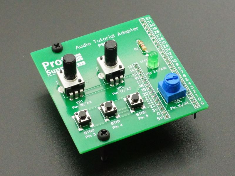
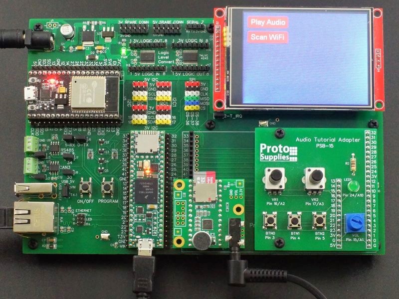
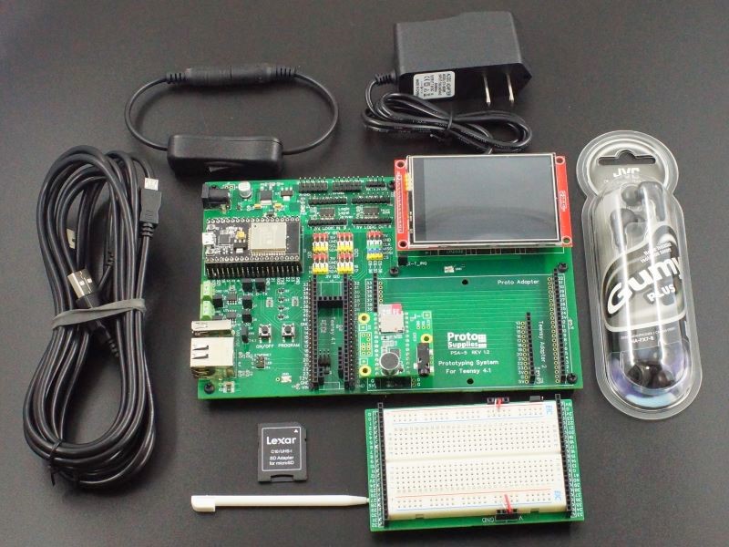
The Audio Tutorial Adapter is designed to be used with the Prototyping System for Teensy 4.1 baseboard. It provides the user controls to go through the Audio Tutorials and Workshop. These tutorials are based on the original PJRC Advanced Microcontroller Audio Workshop.
The adapter can also be used to provide general purpose pushbuttons, potentiometers and an LED for other experiments as well.
Note: This adapter is not compatible with the Project System for Teensy 4.1 baseboard due to pin conflicts.
The Audio Tutorial Adapter is available in two versions:
Kit: One is in a kit form. All components are thru-hole and fairly easy to solder with basic soldering skills.
Fully Assembled: The other is a fully assembled version that is ready to plug into the Prototyping System for Teensy 4.1 baseboard.
Package Includes:
- Audio Tutorial Adapter (Kit or Fully Assembled)
- 2 M3 nylon standoffs, screws and nuts
KEY FEATURES OF AUDIO TUTORIAL ADAPTER:
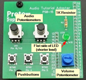
- 3 pushbuttons
- 2 Audio 10K potentiometers
- 1 10K thumb potentiometer
- LED with current limiting resistor
- Nylon standoffs for supporting the board
Assembling the kit version
Assembling the board is straightforward since all components are thru-hole.
The only component that you have to be careful about orientation is the LED. The flat side with the shorter lead goes toward the Pin 24/A10 silkscreen.
For ease of soldering and to minimize the risk of melting plastic, it is generally best to solder the resistor, LED and blue potentiometer first, then solder on the headers, then the pushbuttons and finally the tall audio potentiometers.
Here are a little more detailed instructions.
- Bend the leads of the 1K resistor close to the body and insert it into the R2 location. Orientation doesn’t matter. Turn the board over and bend the leads on the bottom side of the board to hold the resistor in place. Then clip the leads and solder. You can also clip the leads after soldering if you prefer.
- Insert the green LED into location LED1. Ensure the flat side of the LED with the shorter lead faces the Pin 24 / A10 silkscreen. Bend the leads on the bottom side of the board to hold the LED in place and flat to the board. Then clip the leads and solder.
- Insert the blue potentiometer with 3 pins into the location VOL. Bend the leads on the bottom side of the board out in different directions to hold the potentiometer in place. Then clip the leads and solder
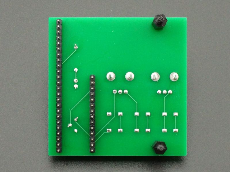
- Next install the 14-pin and 24-pin headers on the bottom side of the board. This is easiest if the headers are inserted into a solderless breadboard first to hold them in place. Install the board over the headers and solder the pins on the top side of the board. Press down on the board near the header when soldering the first pins to ensure the board and headers are perpendicular to each other. Use care not to contact the other components already soldered to the board with the soldering iron to avoid melting them.
- Insert the 3 pushbutton switches into the BTN0, BTN1 and BTN2 locations. The spacing of the leads is slightly wider in one direction and the wider spacing goes top to bottom on the board. Ensure all 4 leads are inserted into the 4 holes and push the switch flat to the board. The formed leads will hold the switch in place. Solder the leads.
- Next insert the 2 audio potentiometers in VR1 and VR2 locations. Squeeze the large metal tabs slightly together with the fingers while inserting them. The tabs will hold them in place while they are being soldered.
- Finally add the standoffs. The screws should be inserted through the top of the board and screwed into the female end of the standoffs. When the board is inserted into the Prototyping System for Teensy 4.1, the male end of the standoffs will go into holes in the baseboard. You can leave the nuts off to make it easier to remove the board if it is being used temporarily
Using the Audio Tutorial Adapter for Teensy
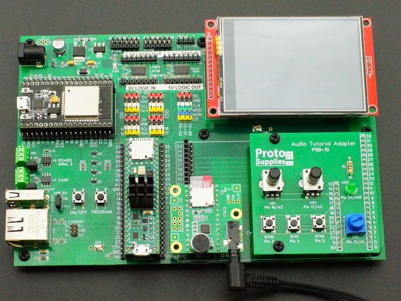
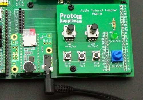
The Audio Tutorial Adapter is designed to fit on the right side of the Proto Adapter area of the Prototyping System for Teensy 4.1 baseboard. The nylon standoffs support the left edge of the board since it hangs out in space. Though nylon nuts are provided to lock the adapter to the baseboard if desired, they generally are not needed since the board just needs support when pressing down on it.
The Teensy 4.x (Rev D) Audio Adapter fits into the adapter slot on the left side of the Proto Adapter area.
The Audio Tutorials and Workshop under the Learn main menu, feature many aspects of working with audio systems including polyphonic playback, recording, synthesis, analysis, effects, mixing, simultaneous inputs & outputs and flexible internal signal routing.
These tutorials closely follow the original PJRC source material but have been modified to use alternate pins to avoid conflict with the baseboard and in some cases have some additional functionality added, such as to make use of the built-in LCD.
The circuit changes from the original PJRC breadboard setup consist of the following:
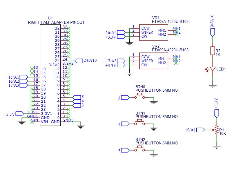
- The pushbuttons have been moved from Teensy pins 0-2 to pins 3-5 to avoid conflict with the ESP32-S and LCD interrupt output on the baseboard.
- An LED as been added to pin 24. This is used instead of the built-in LED on pin 13 of the Teensy 4.1 to avoid conflict with that pin since it is also used by the Audio Adapter SD card.
- A volume control potentiometer has been added to the board to be used in place of the one normally mounted on the Teensy Audio Adapter since that one is harder to come by or use in this setup. This potentiometer is connected to the same pin 15 as the one on the Audio Adapter would be.
Further Reading:
PJRC Audio Forum – Excellent source of technical information for using audio with Teensy.
Notes:
- None
Technical Specifications
| Operating Voltage | 3.3V typical |
| Board Dimensions (PCB) | 63.5 x 63.5mm (2.5 x 2.5″) |
| Country of Origin | Designed and final assembly in USA, Manufactured in China |
You may also like…
-
Select options This product has multiple variants. The options may be chosen on the product page
Prototyping System For Teensy 4.1
$69.95 – $149.95Platform for working with the powerful Teensy 4.1

