ATmega328P with Bootloader
$7.95
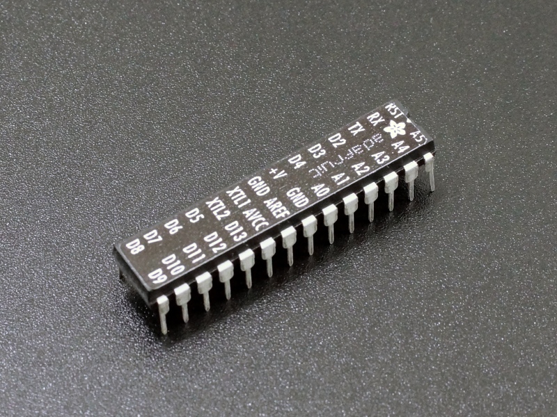
Includes Arduino Uno bootloader and pinout label
25 in stock
Description
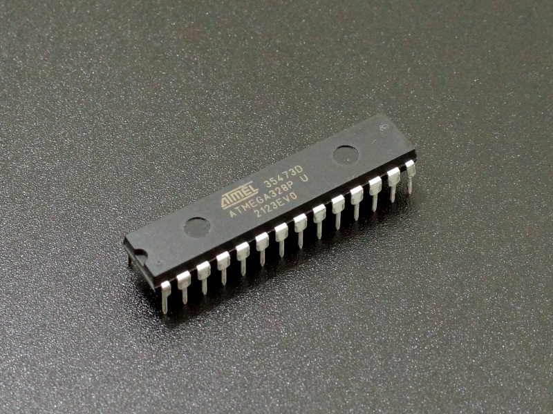
These are ATmega328P microcontroller ICs in the 28-pin DIP package as used on the Arduino Uno. They have the Uno bootloader pre-loaded to make it easy to get up and running and we even throw on a pinout label for easier wiring on DIY projects. They can also be used to repair damaged chips on existing Uno boards.
PACKAGE INCLUDES:
- ATmega328P 28-pin DIP IC w/ bootloader with pinout label
KEY FEATURES OF ATmega328P IC:
- 28-pin DIP package is breadboard friendly
- Runs at up to 20Mhz
- 32KB Flash memory
- 23 total I/O lines including 6 PWM and 6 10-bit ADC
- SPI / I2C and Serial ports
- Uno bootloader preloaded for easy programming
- Adafruit pinout label applied for easier wiring
- 4.5 – 5.5V Operation
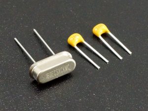
To get up and running with a DIY project and be able to download programs with the Arduino IDE, you just need a breadboard and a few parts like a 16MHz crystal and load capacitors and a USB to serial port adapter to download programs to it.
There is something very satisfying about building your own microcontroller circuit from scratch, so we are including instructions for building a basic bare-bones system below that can easily be expanded.
BUILDING YOUR OWN BARE-BONES UNO
Building a bare-bones Uno using this chip is easy to do and provides a starting platform that can be expanded upon for more full featured applications.
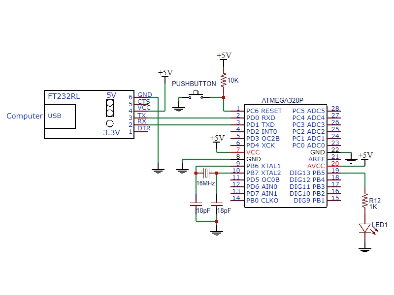
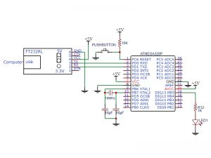
To get the chip up and running, you will need to supply 5V power, a 16MHz clock signal, provide a way to reset the chip and a means to interface between the chips serial lines and the USB port on your computer so you can download a program into the part.
The bootloader on the chip is a small program that looks to see if a program is ready to be downloaded when the part comes out of reset. If a new program for download is found, it is downloaded and executed. If it is not found, the bootloader runs any program that is already stored in memory.
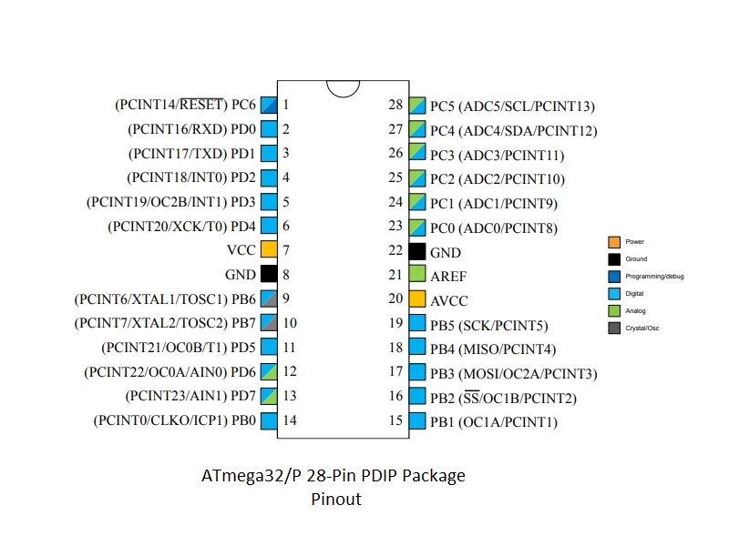
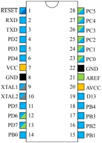
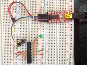
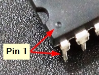
For our example here, we are using a solderless breadboard. To begin, insert the ATmega328P chip into the breadboard. Take note that pin 1 is the pin next to the small dimple in the top of the chip and labeled RST for reset.
Connecting Power and Ground
We are going to use power from the USB port to power our setup. For now, connect the following pins on the ATmega328P to the power and ground rails on the breadboard.
- Connect ground to pins 8 & 22
- Connect power to pins 7 & 20
If you have an extra 0.1uF ceramic capacitor laying around, you can place it across power and ground at pins 7 & 8 to provide some power supply bypassing, but its not really needed for our simple circuit here.
Connecting the 16MHz Crystal
Though the chip can run up to 20MHz, much of the Arduino software assumes a 16MHz clock for timing purposes, so we will stick with that to keep life simple.
- Connect a 16MHz crystal across pins 9 & 10.
- Connect two 18pF crystal load capacitors between pin 9 & ground and pin 10 & ground.
If you are using a crystal from somewhere else, it may require a different value for the capacitors, but most work with caps in the 18-22pF range.
Hooking Up a Reset Circuit
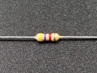
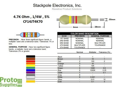
Connect a 4.7K to 10K resistor from pin 1 (Reset) to 5V. This pulls the pin HIGH and avoids accidental resets from having a floating pin.
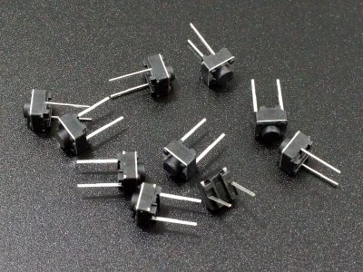
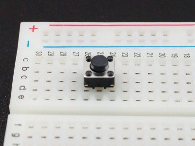
Connect a normally open pushbutton switch from pin 1 to ground so that you can initiate intentional resets during the software download process. If you don’t have a switch handy, you can use a jumper wire to momentarily ground the reset pin, but a button helps make the download process go a little smoother.
Hook Up an LED
Though not technically necessary, having an LED to blink will help us determine if our setup is running successfully.
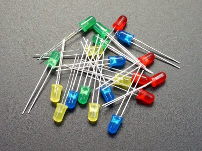
Connect an LED and series current limiting resistor of around 330 ohms between pin 19 and ground. Observe the correct polarity on the LED and ensure that the cathode lead (shorter of the two leads) is attached to ground.
This duplicates the Uno on-board LED which is attached to the Uno D13 board pin (which is actually connected to the ATmega328P pin 19 as we have done here.
Hook Up the Serial Port to USB Port on Computer
The ATmega328P uses TTL level serial TX/RX pins for communication. To talk to the chip with our computer, we will need a USB to TTL Serial interface adapter.
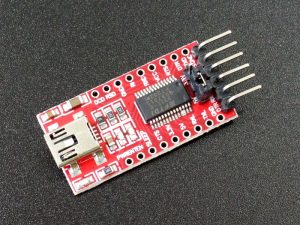
We are using the FT232RL USB to TTL Serial Interface Adapter in our example, but you may already have something similar on-hand that will work. These adapters are commonly used with small microcontroller boards that don’t have built-in USB ports.
If there is a voltage option on the interface adapter to select between 3.3V and 5V, ensure 5V is selected.
- Connect RX on the adapter to pin 3 (TX) on the chip.
- Connect TX on the adapter to pin 2 (RX) on the chip.
- Connect ground on the adapter to the ground rail on the breadboard.
- Connect VCC on the adapter to the power rail on the breadboard.
Once the USB cable is inserted into the FT232RL, power will be applied to the breadboard and the circuit will be powered up.
Programming Your New Microcontroller
If you have the FT232RL driver installed on your computer, you should see your new circuit come up as a COM port in the Arduino IDE as a normal Uno would. Select that COM port and ensure that Arduino Uno is selected for the board type.
If this is the first time using the FT232RL or other adapter, you may need to download a driver so that the computer can recognize it. The driver for the FT232RL module can be downloaded from: http://www.ftdichip.com/Drivers/VCP.htm.
Open the ‘Blink’ example program in the IDE.
Our simple circuit here does not have an auto reset feature for downloading like a normal Uno board, so we will need to manually reset the ATmega328P device to initiate the download.
- On the IDE, press the Download button.
- Once the program starts to compile, press and hold the reset button on your circuit.
- After the program has been compiled and the IDE reports ‘Uploading….’ at the bottom of the window, release the reset button
- You should see the RX/TX lights on the FT232RL momentarily flash as the program is downloaded and the IDE should now report ‘Done Uploading’. The LED on the breadboard should now start to flash at 1 second intervals as the program begins execution.
If the ‘Done Uploading’ doesn’t appear and the download appears to hang or timeout instead, try downloading again and adjust the timing of when you release the reset button.
BEFORE THEY ARE SHIPPED, THESE CHIPS:
- Have bootloader installed from the current Arduino IDE
- Handy Adafruit I/O pinout label is applied
FURTHER READING:
Arduino as ISP and Arduino Bootloaders
From Arduino to a Microcontroller on a Breadboard
Building an Arduino on a Breadboard
Notes:
- None
Technical Specifications
| Microcontroller | ATmega328P |
| Operating Voltage | 4.5 – 5.5V |
| Digital I/O Pins | 14 |
| PWM I/O Pins (Shared with Digital I/O) | 6 |
| Analog Input Pins | 6 |
| DC Current per I/O Pin | 20mA |
| Flash Memory | 32 KBytes |
| SRAM | 2 KBytes |
| EEPROM | 1 KBytes |
| Clock Speed | 20MHz (16MHz typical) |
| SPI Port | 1 |
| I2C Port | 1 |
| Serial Port | 1 |
| Data Sheet | ATmega328P |

