


X9C103S Digital Potentiometer Module
$3.95
10kΩ digitally controlled potentiometer with 100 selectable wiper taps
7 in stock
Description
The X9C103S Digital Potentiometer Module is a 10kΩ digitally controlled potentiometer with 100 selectable wiper taps and non-volatile storage of the current tap point.
PACKAGE INCLUDES:
- X9C103S Digital Potentiometer Module
- 2x male header strips
KEY FEATURES OF X9C103S DIGITAL POTENTIOMETER MODULE:
- 0-10kΩ with 100 steps
- Use as 3-terminal potentiometer or 2-terminal variable resistor
- 3-wire control interface
- Up to ±5V across the potentiometer end-points
- 4.4mA current sink or source capability
- Red power LED is lit when power is applied
- 5V logic compatible.
Digital potentiometers are commonly used to allow a uC to control the calibration or adjustment of a device rather than having a human twiddle a potentiometer knob. This can be done 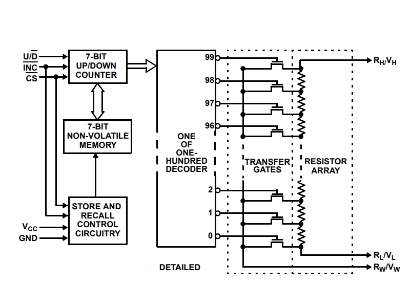 automatically such as in the case where the uC is monitoring a voltage using ADC and adjusting the pot to hit a target voltage or in response to user input such as to control the volume of an audio amplifier.
The potentiometer has 100 steps, so if it is connected across 5V, the step resolution of the wiper output will be approximately 5V/100 steps = 50mV.
The two ends of the potentiometer can be connected to voltages that span the range of up to -5V to +5V.
The maximum output current sink/source capability is 4.4mA. Ensure that is not exceeded in the circuit you are using it in.
3-Wire Interface
The module has an easy to use 3-wire interface that allows the device to be selected, direction of travel of the wiper to be set and the wiper incremented in the direction chosen. It can also optionally save the last setting so that it will be restored after a power cycle.
It is not a true communication interface and it is not possible to read the current setting back out of the device. This may seem like a major limitation, but it mimics how a typical potentiometer is used. You don’t set a potentiometer to a particular resistance value, rather you adjust it to achieve a particular affect depending on the circuit it is being used in.
Module Assembly
This module comes with the headers loose. This allows you to configure the module to meet your particular requirements such as which side of the board you want the header on or if you want to solder on wires to make the connections.
Note that the spacing of the headers on the two ends of the boards are not exactly on 0.1″ centers. For use with breadboards, we put the 5-pin header on the bottom so that the module can plug directly into the breadboard and we put the 3-pin header on the top of the board where connections can be made using female jumpers.
Module Connections
The connections to the module are fairly straightforward.
- Supply 5V power and ground from the MCU to power the module
- Connect the 3 control pins to any 3 digital pins on the MCU.
- Connect the two ends of the potentiometer to 5V and ground or any two voltages that fall in the range of ±5V.
- Connect the wiper output of the pot to where it needs to go. In our example below, we connect it to an analog input on the MCU to see what it is doing.
1 x 5 Header
- VCC = Vcc power (4.5 to 5.5V)
- CS = Chip Select. Active LOW
- INC = Increment. Pulsing this pin low causes the wiper to move on the negative (falling) edge of the pulse
- U/D = Up / Down. Determines the direction of travel of the wiper when the module is incremented. Logic HIGH moves the wiper UP and logic LOW moves the wiper down.
- GND = Ground
1 x 3 Header
- VL = Voltage Low is the voltage for the lower end of the potentiometer. This is normally ground or the lower of two voltages.
- VW – Voltage Wiper is the voltage output of the adjustable wiper contact
- VH – Voltage High is the voltage at the upper end of the potentiometer. This is normally the higher voltage.
Note that just like a regular potentiometer, you can switch the voltages between VL and VH as to which one is more positive, but doing so will reverse the direction of the U/D movement.
OUR EVALUATION RESULTS:
These modules have good build quality and generally work well. It would have been nice if the header layout was on 0.1″ centers but that is not a major limitation as long as you don’t solder both headers to the bottom of the module and then wonder why it won’t plug into a breadboard very well. You can mount both on the bottom side if you first put them into a breadboard and then solder them in place at a slight angle or do as we have and solder the potentiometer contacts on the top side.
The back of the board shows some incorrect voltage info that can be ignored. The chip is specified to operate at a VCC of 5V ± 10%, so cannot operated down to 3V as per the silkscreen. The VL and VH terminals can both handle the full range of -5V to +5V
The program below is a simple program that allows you to control the device directly. There are libraries available for this device but the interface is simple enough that we don’t bother to use one. In the program, entering a ‘U’ causes the wiper to be incremented UP by one. Entering a ‘D’ causes the wiper to be decremented DOWN by one. ‘S’ causes the device to save the current setting.
We are connecting U/D to pin 8, INC to pin 9 and CS to pin 10, but these can be reassigned to any 3 digital pins.
We are connecting the pot across 5V and ground and the wiper output is being input to A0, but this can be any analog input pin.
X9C103S Digital Potentiometer Test Program
/*
  Exercise X9C103S Digital Potentiometer
  Uses Serial Monitor window to issue commands for controlling the pot and
  also observing the results.

  The 3 control lines are attached to any digital Pins pins on uC.  We
  are using pins 8,9 and 10.

  Pot connections:  VL = ground, VH = 5V, VW wiper is connected to analog input A0

  Commands
  --------
  U = Increase wiper setting
  D = Decrease wiper setting
  S = Save current setting into memory for recall after power cycle
*/
const float V_REF = 5.0;          // Change if using different Vref
const int UP = 0;
const int DOWN = 1;
const int UD_PIN = 8;            // Goes to X9C103P U/D pin - Up = HIGH, Down = LOW
const int INC_PIN = 9;           // Goes to X9C103P INC pin - active falling edge
const int CS_PIN = 10;           // Goes to X9C103P CS pin - active LOW
const int WIPER_PIN = A0;        // Goes to X9C103P VW pin - Analog voltage output of pot
float voltage = 0;
//===============================================================================
//  Initialization
//===============================================================================
void setup() {
  pinMode (CS_PIN, OUTPUT);
  pinMode (UD_PIN, OUTPUT);
  pinMode (INC_PIN, OUTPUT);
  Serial.begin(9600);

  digitalWrite(INC_PIN, HIGH);
  digitalWrite(CS_PIN, LOW);                  // Enable the X9C103P chip
  Serial.print ("Initial Voltage Setting: ");
  PrintVoltage();                             // Print X9C103P power up value
}
//===============================================================================
//  Main
//===============================================================================
void loop() {
  if (Serial.available()) DoSerial();  // Just loop looking for user input
}
//===============================================================================
//  Subroutine to handle characters typed via Serial Monitor Window
//===============================================================================
void DoSerial()
{
  char ch = toupper(Serial.read());   // Read the character we received
  // and convert to upper case
  switch (ch) {
    case 'S':                         // Save settings
      digitalWrite(INC_PIN, HIGH);
      digitalWrite(CS_PIN, HIGH);
      delay(100);
      digitalWrite(CS_PIN, LOW);
      Serial.println("Setting Saved");
      break;
    case 'U':                         // Increment setting
      Move_Wiper(UP);
      Serial.print("Incrementing Value");
      PrintVoltage();
      break;
    case 'D':                         // Decrement setting
      Move_Wiper(DOWN);
      Serial.print("Decrementing Value");
      PrintVoltage();
      break;
    default:
      break;
  }
}
//===============================================================================
//  Subroutine to read ADC and print to the Serial Monitor Window
//===============================================================================
void PrintVoltage()
{
  int sampleADC = analogRead(WIPER_PIN);      // Take reading on wiper pin
  float volts = (sampleADC * V_REF) / 1023.0; // Convert to voltage
  Serial.print("   ADC = ");
  Serial.print(sampleADC);
  Serial.print("  Voltage = ");
  Serial.println(volts, 3);
}
//===============================================================================
//  Subroutine to move the wiper UP or DOWN
//===============================================================================
void Move_Wiper(int direction)
{
  switch (direction) {
    case UP:
      digitalWrite(UD_PIN, HIGH); delayMicroseconds(5);  // Set to increment
      digitalWrite(INC_PIN, LOW); delayMicroseconds(5);  // Pulse INC pin low
      digitalWrite(INC_PIN, HIGH);
      break;
    case DOWN:
      digitalWrite(UD_PIN, LOW); delayMicroseconds(5);   // Set to decrement
      digitalWrite(INC_PIN, LOW); delayMicroseconds(5);  // Pulse INC pin low
      digitalWrite(INC_PIN, HIGH);
      break;
    default:
      break;
  }
}
BEFORE THEY ARE SHIPPED, THESE MODULES ARE:
- Sample tested per shipment
Notes:
- None
Technical Specifications
| Operational Ratings | ||
| Vcc | 5V ±10% | |
| VVH | VH Terminal Voltage | -5V to +5V |
| VVL | VL Terminal Voltage | -5V to +5V |
| IW | Wiper Current | ± 4.4mA |
| Wiper Tap Points | 100 | |
| Resistance | End-to-End | 10kΩ ±20% |
| Wiper | 40Ω (typ) | |
| Dimensions | L x W (PCB) | 27 x 14mm (1.1 x 0.55″) |
| Country of Origin | China | |
| Datasheet | Renesas / Intersil | X9C Series |