WS2812 Addressable RGB LED Stick Module
$1.95 Original price was: $1.95.$1.29Current price is: $1.29.
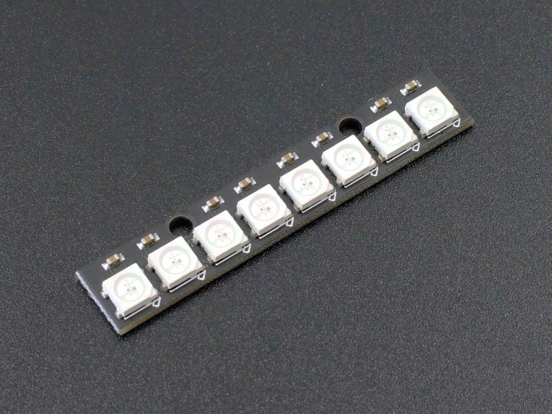
Stick module combines 8 WS2812 addressable LEDs
89 in stock
Description
This ‘stick’ of 8 WS2812 addressable RGB LEDs can be used to experiment with addressable LEDs or to create bar graphs, Night Rider Kitt light bar or other LED displays. The modules can be daisy-chained together to create larger displays.
PACKAGE INCLUDES:
- WS2812 Addressable RGB LED Stick Module
KEY FEATURES OF WS2812 ADDRESSABLE RGB LED STICK MODULE:
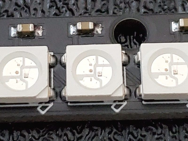
- RGB SMD LED in 5050 (5 x 5mm) package (x8)
- Built-in WS2811 LED drivers
- High brightness
- Fully addressable using 1-wire interface
- 4-7V operation
These LEDs are the same type that are sold as NeoPixels where each LED is separately addressable using a serial bus.
The communication used with the LEDs is a 1-wire interface specific to these devices. There are several libraries available to handle the interfacing details including the Adafruit NeoPixel library and the more advanced FastLED library, both of which are supplied with the Arduino IDE.
There are no specific addresses for the LEDs, rather the color data for each is sent down the wire sequentially with the first LED taking the first color data that comes down the wire, the second LED takes the second color data and so on. After all LEDs are updated, a global command is given to display the new data.
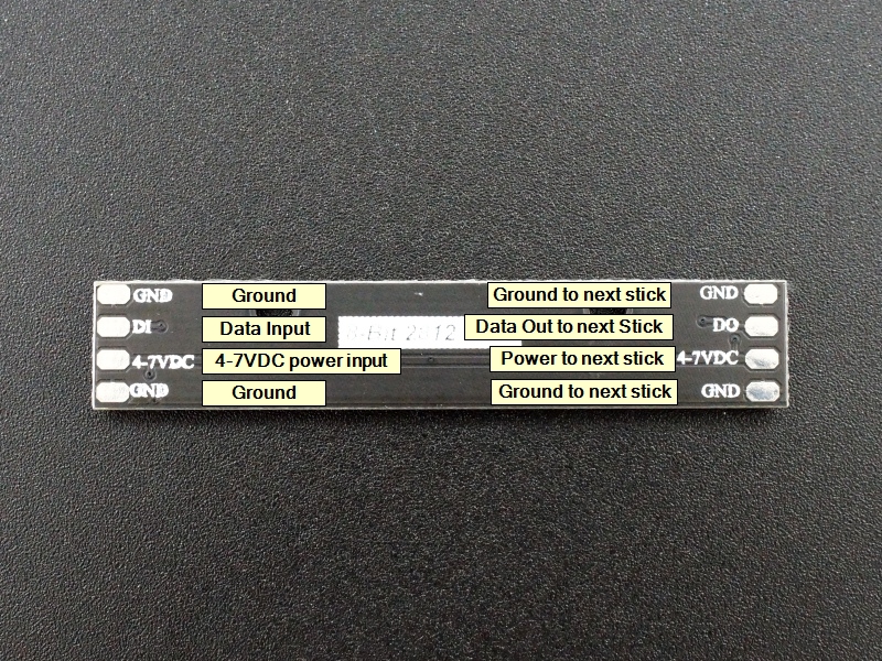
The LEDs are mounted on a board a little over 2″ long. There are solder pads on the back of the board on both ends for connecting wires or headers to. One end is the input and the other end allows the power, ground and data line to be connected to the next module if it is used.
There is no inherent limit in the number of LEDs that can be driven in a chain but several practical limitations will limit the number of LEDs that can be used in an application.
- Power: If driven directly off the power from an MCU like an Arduino, that will limit the number of LEDs that can be driven. This is impacted greatly by the brightness that the LEDs are set to. If using a separate power supply, that removes the basic limitation though multiple power feeds may be required to power large chains in separate sections.
- Processor speed: Updating the LEDs require fairly precise timing of the data line. The more LEDs there are, the more processing time is required to update the string. Faster MCUs can handle more LEDs without slowing updates down.
- RAM: The software uses RAM for LED pixel information. More LEDs = more RAM required. This limitation will vary greatly on the MCU being used to drive the LEDs but is not a concern for most small to medium projects.
The WS2812 is rated for 4-7V operation. We have experimentally run these strips at 3.3V power and logic levels and they continued to work OK.
The LED brightness is programmable and quite bright when run at full power. A single stick can be run off a typical MCU power without any problem. In the example below, at full brightness the stick draws a maximum of about 140mA. With the LEDs displaying white at full brightness which is the worst case power consumption mode, the maximum current draw increases to about 340mA.
When driving a long distance, it is recommended to insert a 330-470 ohm resistor on the DI line between the microcontroller and the first LED to dampen back reflections with the resistor at the LED end of the wire. For breadboard type use, that is not necessary, but won’t hurt.
Module Connections
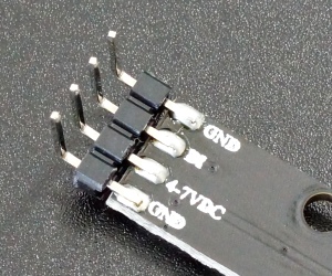
There is two 4-pin solder locations on the back of the assembly. The pins may be labeled in a couple of different ways, but the functionality is the same.
1×4 Header Location Left Side (inputs)
- GND = Ground
- DI / IN = Data In – Connects to a digital output pin on the MCU if first stick, or connects to DO of previous stick in chain.
- 4-7VDC / VCC = Connect to 4-7V power.
- GND = Ground
1×4 Header Location Right Side (outputs)
- GND = Ground connects to GND on next stick
- DO / OUT = Data Out – Connects to DI on the next stick in chain.
- 4-7VDC / VCC = Connect to 4-7V input of next stick in chain.
- GND = Ground connect to GND on next stick
OUR EVALUATION RESULTS:
LEDs tend to be fun to play with in general and RGB LEDs are the most fun of all. With regular LEDs, you can turn them on and off, blink them or pulse them rapidly to change the perceived brightness. With RGB LEDs, you can also add playing with color blending which allows you to create pretty much any colors of the rainbow. The downside to discrete RGB LEDs is that they consume a lot of PWM pins (3 per LED) for control.
These particular devices allow for many to be chained together and operated from a single digital pin and are frequently used for color accents around objects or to create artistic displays of some sort.
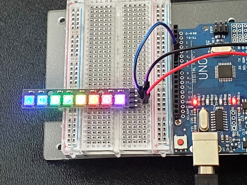
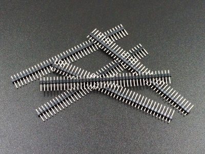
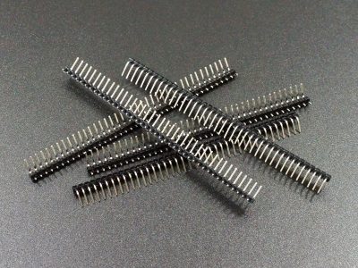
For easy breadboard use, you can solder a right-angle male header to the input pads to lay the board down horizontally as shown to the right. For vertical mounting, a straight male header can be used instead.
The program below uses the Adafruit NeoPixel library to exercise the stick. It is a shortened version of the strandtest example program that is installed when the library is downloaded. It has some of the excess comments removed for brevity. For full comments open the example program.
Connect the DI input to Pin 6 of the MCU. This can be changed to any available data pin. Connect 4-7VDC to 5V and GND to ground. Only one ground needs to be connected.
WS2812 Stick Test Program
// A basic everyday NeoPixel strip test program.

#include <Adafruit_NeoPixel.h>

#define LED_PIN    24  // Pin used to address the LEDs
#define LED_COUNT 300   // How many NeoPixels are attached to the Arduino?
// Declare our NeoPixel strip object:
Adafruit_NeoPixel strip(LED_COUNT, LED_PIN, NEO_GRB + NEO_KHZ800);

//===============================================================================
//  Initialization
//===============================================================================
void setup() {
  strip.begin();           // INITIALIZE NeoPixel strip object (REQUIRED)
  strip.show();            // Turn OFF all pixels ASAP
  strip.setBrightness(25); // Set BRIGHTNESS to about 1/10 (max = 255)
}

//===============================================================================
//  Main
//===============================================================================
void loop() {
  // Fill along the length of the strip in various colors...
  colorWipe(strip.Color(255,   0,   0), 50); // Red
  colorWipe(strip.Color(  0, 255,   0), 50); // Green
  colorWipe(strip.Color(  0,   0, 255), 50); // Blue

  // Do a theater marquee effect in various colors...
  theaterChase(strip.Color(127, 127, 127), 50); // White, half brightness
  theaterChase(strip.Color(127,   0,   0), 50); // Red, half brightness
  theaterChase(strip.Color(  0,   0, 127), 50); // Blue, half brightness

  rainbow(10);             // Flowing rainbow cycle along the whole strip
  theaterChaseRainbow(50); // Rainbow-enhanced theaterChase variant
}

// Fill strip pixels one after another with a color.
void colorWipe(uint32_t color, int wait) {
  for(int i=0; i<strip.numPixels(); i++) { // For each pixel in strip...
    strip.setPixelColor(i, color);         //  Set pixel's color (in RAM)
    strip.show();                          //  Update strip to match
    delay(wait);                           //  Pause for a moment
  }
}

// Theater-marquee-style chasing lights.
void theaterChase(uint32_t color, int wait) {
  for(int a=0; a<10; a++) {  // Repeat 10 times...
    for(int b=0; b<3; b++) { //  'b' counts from 0 to 2...
      strip.clear();         //   Set all pixels in RAM to 0 (off)
      // 'c' counts up from 'b' to end of strip in steps of 3...
      for(int c=b; c<strip.numPixels(); c += 3) {
        strip.setPixelColor(c, color); // Set pixel 'c' to value 'color'
      }
      strip.show(); // Update strip with new contents
      delay(wait);  // Pause for a moment
    }
  }
}

// Rainbow cycle along whole strip.
void rainbow(int wait) {
  for(long firstPixelHue = 0; firstPixelHue < 5*65536; firstPixelHue += 256) {
    strip.rainbow(firstPixelHue);
    strip.show(); // Update strip with new contents
    delay(wait);  // Pause for a moment
  }
}

// Rainbow-enhanced theater marquee. Pass delay time (in ms) between frames.
void theaterChaseRainbow(int wait) {
  int firstPixelHue = 0;     // First pixel starts at red (hue 0)
  for(int a=0; a<30; a++) {  // Repeat 30 times...
    for(int b=0; b<3; b++) { //  'b' counts from 0 to 2...
      strip.clear();         //   Set all pixels in RAM to 0 (off)
      for(int c=b; c<strip.numPixels(); c += 3) {
        int      hue   = firstPixelHue + c * 65536L / strip.numPixels();
        uint32_t color = strip.gamma32(strip.ColorHSV(hue)); // hue -> RGB
        strip.setPixelColor(c, color); // Set pixel 'c' to value 'color'
      }
      strip.show();                // Update strip with new contents
      delay(wait);                 // Pause for a moment
      firstPixelHue += 65536 / 90; // One cycle of color wheel over 90 frames
    }
  }
}
BEFORE THEY ARE SHIPPED, THESE MODULES ARE:
- Sample tested per incoming shipment.
Notes:
- None
Technical Specifications
| Maximum Ratings | ||
| Vcc | 4-7V | |
| IMax | Maximum current draw per strip | 340mA |
| Dimensions | L x W (PCB) | 54mm x 10mm (2.13 x 0.39″) |

