WS2812 Addressable RGB LED Module
$0.60
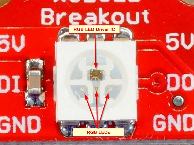
Module combines a WS2811 RGB LED driver IC and RGB LED in the same package.
22 in stock
Description
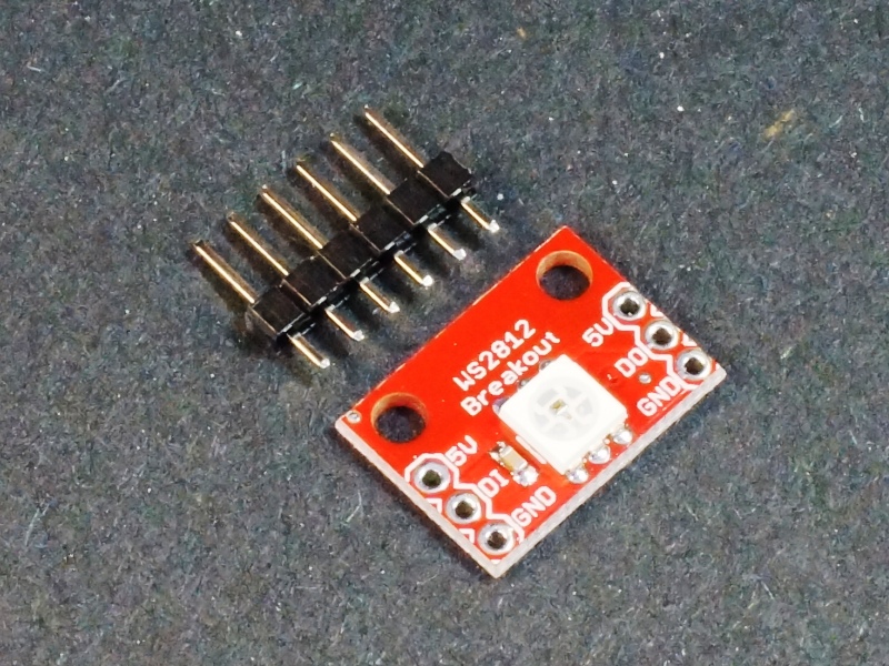
The WS2812 Addressable RGB LED Module combines a WS2811 RGB LED driver IC and RGB LED in the same package.
PACKAGE INCLUDES:
- WS2812 Addressable RGB LED Module
KEY FEATURES OF WS2812 RGB LED MODULE:
- RGB SMD LED in 5050 (5 x 5mm) package
- Built-in WS2811 LED driver
- Fully addressable using 1-wire interface
- 5V compatible
These types of LEDs are commonly used in RGB strip lighting like you find sold as NeoPixels where each LED is separately addressable.
The LED is mounted on a breakout board and operates at 5V which make it handy for experimenting with the parts on a breadboard setup. Headers are supplied separately in case it is desired to wire multiple modules directly together rather than use headers.
The WS2812 can operate at voltages in the range of 5-7V. You will also find the WS2812B for sale which are basically the same but operates at a lower 3-5V range.
The communication used with the LEDs is a 1-wire interface specific to these devices. There are several libraries available to handle the interfacing details including the Adafruit NeoPixel library and the more advanced FastLED library, both of which are supplied with the Arduino IDE.
There are no specific addresses for the LEDs, rather the color data for each is sent down the wire sequentially with the first LED taking the first color data that comes down the wire, the second LED takes the second color data and so on. After all LEDs are updated, a global command is given to display the new data.
The LEDs can draw up to 60mA each though the brightness is controllable through most libraries to keep the power consumption down. If driving more than a few off an Arduino power pin, keep an eye on the power consumption or power directly from a separate 5V power supply.
When driving a long distance, it is recommended to insert a 330-470 ohm resistor on the DI line between the microcontroller and the first LED to dampen back reflections. For breadboard type use, that is not really necessary, but won’t hurt.
Module Connections
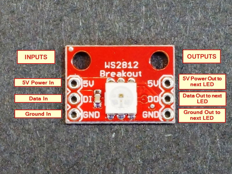
There is two 3-pin header locations on the assembly.
1×3 Header Location Left Side (inputs)
- 5V = Connect to 5V power.
- DI = Data In – Connection to a digital output pin on a microcontroller if first LED, or connects to DO of previous LED in chain.
- GND = Ground
1×3 Header Location Right Side (outputs)
- 5V = Connect to 5V on the next LED in the chain
- DO = Data Out – Connections to the next LED DI in the chain
- GND = Connect to Ground on the next LED in the chain
OUR EVALUATION RESULTS:
LEDs tend to be fun to play with in general and RGB LEDs are the funnest of all. With regular LEDs, you can turn them on and off, blink them or pulse them rapidly to change the perceived brightness. With RGB LEDs, you can also add playing with color blending which allows you to create pretty much any colors of the rainbow. The downside to discrete RGB LEDs is that they consume a lot of PWM pins (3 per LED) for control. These particular devices allow for many to be chained together and operated from a single digital pin and are frequently used for color accents around objects or to create artistic displays of some sort.
These breakout boards are great to experiment with the technology and for that purpose, I recommend getting 2 so that multiple LEDs can be addressed. If you are doing an actual project that requires a lot of these LEDs, then I recommend getting an LED strip that has all the LEDs prewired together which will be a cheaper solution overall.
BEFORE THEY ARE SHIPPED, THESE MODULES ARE:
- Inspected
- Packaged in a resealable ESD bag for protection and easy storage.
Notes:
- None
Technical Specifications
| Maximum Ratings | ||
| Vcc | 5-7V | |
| IMax | Maximum Current Draw per LED | 60mA |
| Dimensions | L x W (PCB) | 18mm x 13mm (0.71 x 0.51″) |


