

Teensy 4.1 For AgOpenGPS
$39.95
Bottom extended reach Ethernet header for AgOpenGPS Baseboards
3 in stock (can be backordered)
Description
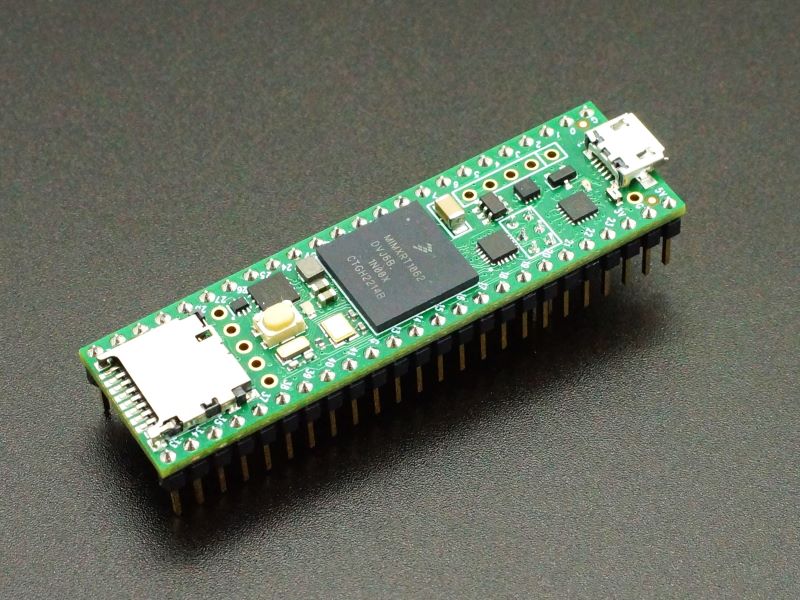
The Teensy 4.1 for AgOpenGPS is the standard Teensy 4.1 with the main pins soldered on and an extended Ethernet male header mounted on the bottom of the module to mate with the female header on the AgOpenGPS baseboard to make it plug-n-play.
Please Note: We keep a small number of each version of the Teensy 4.1 in stock for immediate shipment. Since this item is hand-modified, if you need more than what we show in stock, the website will allow you to backorder the quantity that you need. Back-ordered Teensy 4.1 will typically ship within 1 to 2 business days.
Package Includes:
- Teensy 4.1 configured as outlined below
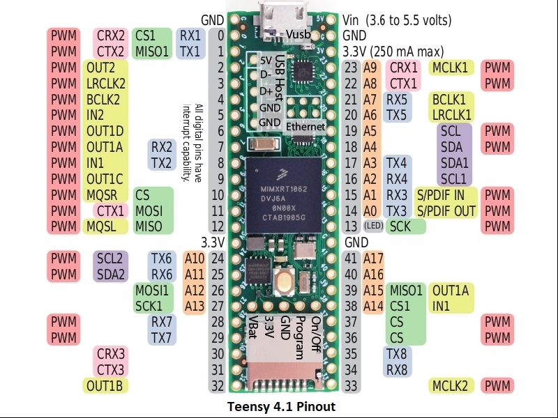
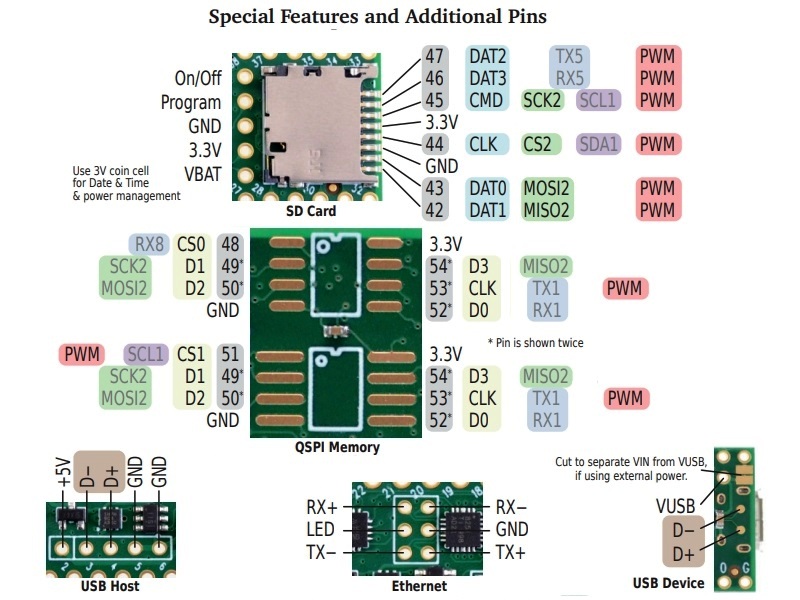
- Handy pinout diagram
The following changes are made to the the base Teensy 4.1 product:
- A 2×3 2mm extended reach male header is mounted at the Ethernet connector location on the bottom side of the Teensy 4.1

AgOpenGPS VUSB Pin
- Standard 24-pin gold male headers are installed
- Note: We are now adding the VUSB pin for compatibility with the AIO V4.5 boards that have a 2-pin female connector to mate up with it. If used with a board that does not have that 2-pin female header, the pin on the Teensy will just not be connected to anything. We are not cutting the VUSB/VIN trace.

For full details on the Teensy 4.1, please refer to the base Teensy 4.1 Product Page.
Before they are shipped, the Teensy 4.1 has:
- The board is configured as outlined above.
- Board is cleaned of flux
- Blink example is downloaded to verify basic operation
- Packaged in high quality resealable ESD bag for safe storage.
Notes:
- Because of the bottom mounted Ethernet header, these Teensy 4.1 will not work in a solderless breadboard.
- The male ethernet header may either be tin plated or flash gold plated phosphor bronze depending on availability.
Technical Specifications
| Microcontroller | NXP iMXRT0162 ARM Cortex-M7 |
| Clock Speed | 600MHz nominal (Optionally 24MHz to 1.008GHz w/ cooling) |
| RAM | 1MB (1024K) |
| FLASH | 8MB (8192K) |
| QSPI PSRAM Chip Location | 8MB PSRAM or empty |
| QSPI Flash Chip Location | 16MB, 128MB or 256MB FLASH or 2nd 8MB PSRAM or empty |
| I/O Logic Levels | 3.3V |
| 5V I/O Compatibility | None |
| Output Pin Drive Current | 10mA |
| DC Current that can be drawn from 3.3V Pin | 250mA maximum |
| Operating Voltage | 3.6 – 5.5V on VIN or VUSB pin |
| Typical Operating Current | 100mA typical @ 600MHz |
| Built-in LED | Attached to digital I/O Pin 13 |
| USB Connector Style | Micro-B Female |
| Board Dimensions (PCB) | 61 x 18mm (2.4 x 0.7″) |
| Country of Origin | USA |
| Mfr | PJRC |
| Datasheet | NXP IMXRT1060 |
| Reference Manual | NXP IMXRT1060 Reference Manual |