TCS34725 RGB Color Sensor Module
$7.95
High precision RGB and ambient light sensors, white LED light source and I2C interface.
8 in stock
Description
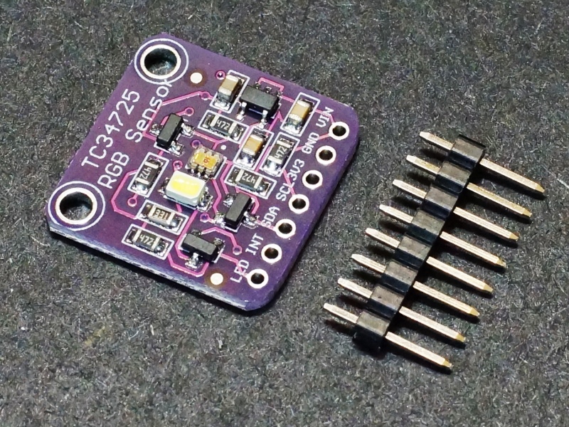
The TCS34725 RGB Color Sensor Module incorporates high precision RGB and ambient light sensors, white LED light source and I2C interface.
PACKAGE INCLUDES:
- TCS34725 RGB Color Sensor Module
- Male header strip
KEY FEATURES OF TCS34725 RGB COLOR SENSOR MODULE:
- Separate Red/Green/Blue light intensity sensors
- Ambient (clear) light intensity sensor
- IR light blocking filter
- Integrated logic controlled white LED light source
- 3,800,000:1 dynamic range
- Adjustable gain and integration time
- Interrupt output available based on predefined lighting thresholds
- I2C interface
- 3.3 or 5V operation
Operational Theory
The sensor works by shining a white light on an object and measuring the amount of red, green, blue and white light that is reflected from the surface of that object.
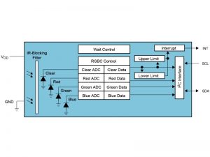
The measurements are taken using a a 3 x 4 matrix of sensors that have red/green/blue color filters in front of them. It also measures the overall intensity of the reflected light using a clear filter over three of the sensors. The entire sensor array has an IR filter over it that minimizes the effect of IR light on the readings.
The analog sensor outputs are converted to 16-bit digital values using 4 integrating ADCs. These sensor digital values are then available to the MCU via the I2C bus.
There are 2 main settings that can be configured to affect the readings and optimize them for a particular application.
Gain Setting: The gain setting can be set to 1X, 4X, 16X or 60X. Higher gain settings may help read the color correctly under lower light conditions but it may also increase the noise level of the reading.
Integration Time: The integration time is the length of time used for taking the sample. Longer integration times may provide better accuracy in some applications. The integration time 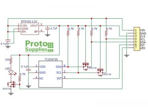
If the interrupt has been enabled, when the measured values exceed an upper or lower threshold values set for the interrupt, the open-collector output will be driven LOW. Since it is an open-collector output, a pull-up resistor is needed on the INT line to pull it HIGH when it is not being driven LOW. This can usually be implemented by enabling an internal pull-up on the uC data pin.
The on-board white LED is used to illuminate the object being measured and it can be controlled via the LED pin on the module. When the pin is left floating, the LED will be illuminated. If it is desired to have it permanently off, the pin can be grounded. The pin can also be attached to a digital output on the MCU and turned on/off when samples are being taken.
I2C Interface
The module communicates via a standard I2C interface. The I2C address is fixed at the address of 0x29.
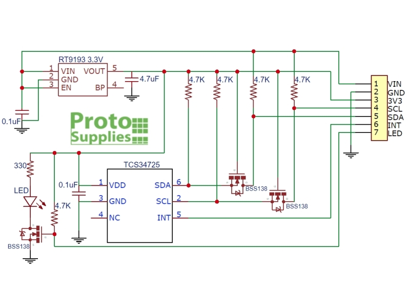
The module includes MOSFETs and pull-up resistors to provide level shifting of the I2C SDA and SCL lines so that they will work correctly with both 3.3 and 5V MCUs.
Powering the Module
The module can be powered by either 5V or 3.3V input on the VIN pin on the module.
The TCS34725 sensor operates at 3.3V, so an on-board 3.3V regulator drops higher voltages down to 3.3V needed for the sensor.
A 3V3 pin on the module provides access to the 3.3V output of the regulator if it is needed.
Module Connections
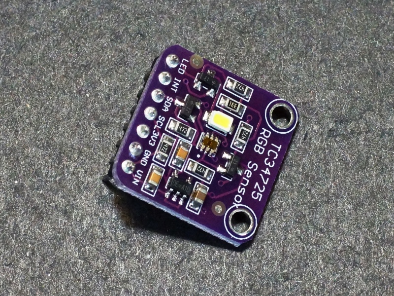
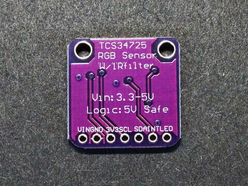
The module brings out the following connections.
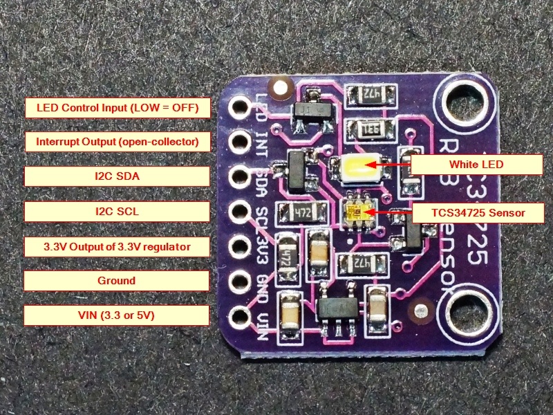
1 x 7 Header
- LED = LED control input. Leave floating for LED always on. Pull LOW to turn LED off
- INT = Interrupt output active LOW. Output is open-collector so requires pull-up resistor. Connects to an interrupt input on the MCU if used.
- SDA = I2C SDA line. Connects to SDA on MCU
- SCL = I2C SCL line. Connects to SCL on MCU
- 3V3 = 3.3V output from the on-board 3.3V regulator
- GND = Ground connects to ground on the MCU
- VIN = Power input. Connects to 3.3V or 5V on the MCU
Module Assembly
The module ships with the male header strip loose. This allows the header to be soldered to the top or bottom of the module depending on the planned use or wires can be used to make the connections.
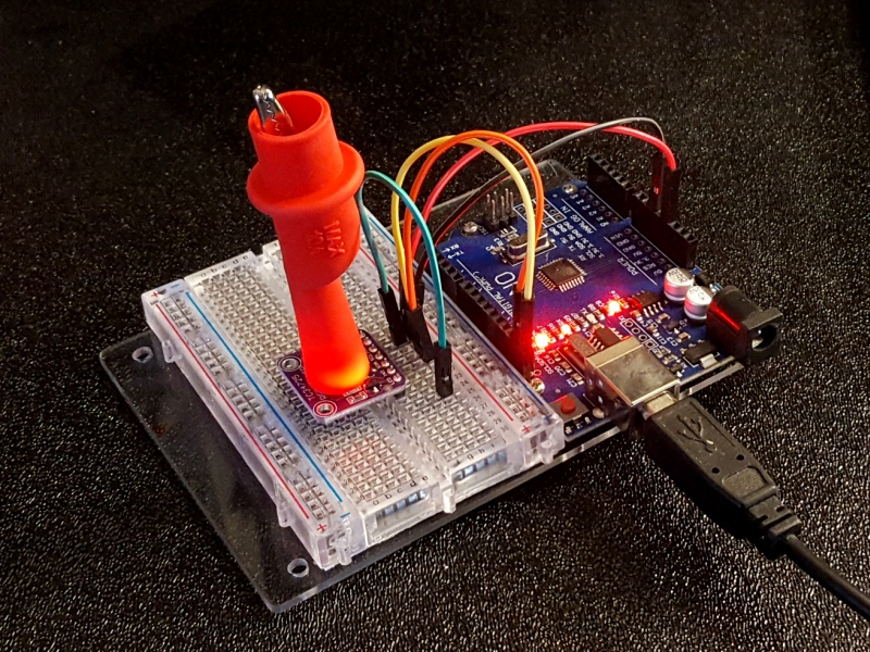
For breadboard use, we put the headers on the bottom. Soldering is easiest if the header is inserted into a breadboard to hold it in position during the soldering process.
OUR EVALUATION RESULTS:
The TCS34725 is one of the best low cost color sensors available but measuring precise color can be a tricky thing as there are many variables involved.
With the Adafruit library that can be downloaded via the IDE, the module is easy to get up and running and reporting basic color data.
In our examples below, first we have a simple program that will report the color data out to the Serial Monitor window. If you place a red object in front of the sensor, you should see the red values increase. This is a good indication that the module is working, but it can be hard to visualize the true color that the sensor is reporting. One way to do this is to plug the reported RGB values into a color program to see the reported color on the computer screen. Here is an example of an on-line tool that is easy to use: https://www.colorspire.com/rgb-color-wheel/
Our example program here is a stripped down version of the colorview sample program that comes with the Adafruit library. That program also sends the color data to an RGB LED to try to recreate the color that the sensor is seeing. You might find that an interesting exercise, but we are just using the color data that is being reported over the serial port which we will visual on the computer screen using Processing software in our 2nd example.
To use this software first load the Adafruit_TCS34725 library. This can be done from within the Arduino IDE.
Connect that module I2C SDA and SCL lines to the same on the MCU. Connect 3.3V or 5V power to VIN and ground to GND. You can ignore the other pins for now.
Once the program is running, open the Serial Monitor window and you will see a stream of data including Clear / Red / Green / Blue and a hex string that represents the color. Put something in front of the sensor to see the affect on the reported numbers.
You may be curious why ’44’ is always the first data that is sent to the Serial Monitor window. This is because when the library checks to see if the sensor is attached, it requests the sensor type and 44 designates the TCS34725 sensor.
TCS34725 Test Program
/*
   Exercise the TCS34725 RGB Color Sensor Module

   Connect SDA on module to SDA on uC and connect SCL to SCL.
   Connect VCC and GND on module to 5V and ground on uC
*/

#include <Wire.h>
#include "Adafruit_TCS34725.h"

// Create instance of tcs object and set integration time to 50mS and gain to 4X
Adafruit_TCS34725 tcs = Adafruit_TCS34725(TCS34725_INTEGRATIONTIME_50MS, TCS34725_GAIN_4X);
//===============================================================================
//  Initialization
//===============================================================================
void setup() {
  Serial.begin(9600);

  if (!tcs.begin()) {                    // Initialize the sensor
    Serial.print("No Sensor Found - Halting Program");
    while (1);
  }
}
//===============================================================================
//  Main
//===============================================================================
void loop() {
  uint16_t clear, red, green, blue;

  delay(60);  // Ensures there is sufficient time between reads

  tcs.getRawData(&red, &green, &blue, &clear);

  Serial.print("C:\t"); Serial.print(clear);
  Serial.print("\tR:\t"); Serial.print(red);
  Serial.print("\tG:\t"); Serial.print(green);
  Serial.print("\tB:\t"); Serial.print(blue);

  // Figure out some basic hex code for visualization
  uint32_t sum = clear;
  float r, g, b;
  r = red; r /= sum;
  g = green; g /= sum;
  b = blue; b /= sum;
  r *= 256; g *= 256; b *= 256;
  Serial.print("\t");
  Serial.print((int)r, HEX); Serial.print((int)g, HEX); Serial.print((int)b, HEX);
  Serial.println();
}
Processing Software
In this 2nd step, we will load the Processing software which creates a small window on the PC monitor and uses that data stream to paint the window with the color that is being reported by the sensor. This makes it much easier and frankly more fun to experiment with the sensor, lighting, light shielding, object positioning, gain and integration values and other variables and immediately see the effect on the detected color. For this purpose, we are just going to leverage the software that comes with the Adafruit library.
If you are not familiar with Processing, it is an application created by Processing.org that looks very similar to the Arduino IDE, but the program that your create using it runs on the PC rather than on an Arduino. This allows you to write a program that runs on the computer and interfaces with the Arduino or other uC over the USB serial port. It is very easy to get up and running using our example here. How to program the Processing software is outside the scope of this writing, but the Processing.org website has many tutorials.
Install the software
First step is to install the Processing software.
Go to the Processing.org and download the version that you need for your computer. They support Windows, Mac and Linux. https://processing.org/download/
Once it is downloaded, open the zip file and drag the processing-3.4 folder to some convenient location on your computer. This folder name will change depending on the current version of the software.
That completes the software installation
Run the Processing software
Open the folder and double-click the processing.exe application to run it.
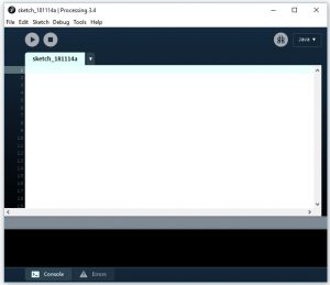
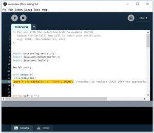
When you launch the software, you will see a window that looks like this. It looks very similar to the Arduino IDE.
Open the colorview Processing software that came with the Adafruit library
Go to File/Open and navigate to your Arduino library folder. Select Adafruit_TCS34725/examples/colorview/processing/colorview/colorview.pde.
Files with the .pde suffix are Processing files. Open the colorview.pde file.
Modify the COM port
We will need to make one small change to the Processing colorview program which is to tell it which COM port we want to use. This should be the COM port that we are using with the IDE to talk to the Arduino.
In the setup() section find this line which is highlighted below: port = new Serial(this, “COM4”, 9600);
Change COM4 to match the COM port that you are using with your IDE to talk to the Arduino.
Run the Processing Software
If you still have the IDE Serial Monitor window open, close it since only one application can access the same COM port at the same time.
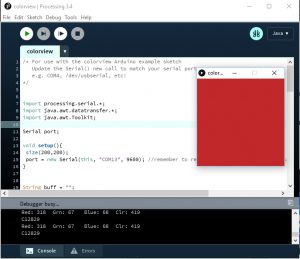
Now press the ‘Play/Debug’ arrow in the upper left area of the Processing window. The arrow will turn green to tell you the program is running and you should see a small window open that will display the color being reported by the sensor. The raw data will also be displayed in a small window at the bottom of the application. You can now try different things with the sensor and see the immediate affect in the window on the PC.
Switching between the Arduino IDE and Processing applications
It is easy to switch between the applications such as if you want to download new code to the Arduino and then see the effect in the Processing window. Just remember that only one application can access the COM port at the same time.
To go from Processing to IDE, just turn off the Processing software by clicking the square ‘STOP’ button on the window. The IDE can now access the COM port to download a new program or to open the Serial Monitor window.
To go from IDE to Processing, just close the Serial Monitor window if it is open and you can then run the Processing software again.
Practical Use Considerations
As you use the module, you will find that achieving precise color detection presents some challenges. Here are a few things to keep in mind.
- The sensor detects color from its entire field of view. If the sensor is just running with no target object in front of it, the color reported tends to be a muddy brown because it is combining all the colors in its field of view.
- The sensor preforms best when the object to be detected is very close to the sensor. This is partially because the object blocks out the ambient light. Flat black light shielding can be used to help shield the sensor from extraneous colors. Typically the object should be within 1cm or even placed directly on the sensor.
- The built-in LED helps illuminate the object being detected. Depending on how shiny the object is, the light may create specular reflections on the object. Just like with the human eye, these reflections tend to wash out the color information. Tilting the object in relation to the LED / sensor pair may help improve the color detection.
- The LED during operation heats up and causes the color data to thermally drift somewhat. There is a decision that can be made to intermittently turn on the LED during the color sampling or just leave the LED on all the time. In some cases it may be best to leave the LED off and use an external light source of some type.
- The sensor uses 16-bits of color data, but in most applications including those here, the color data is compressed down to just 8-bits so quite a bit of info is thrown out for the sake of ease of use.
- The sensor software may benefit from a calibration process once placed in a final application.
BEFORE THEY ARE SHIPPED, THESE MODULES ARE:
- Inspected
- Tested using the above program
- Packaged in a resealable ESD bag for protection and easy storage.
Notes:
- None
Technical Specifications
| Operating Ratings | ||
| Vcc | 3.3 – 5.5V | |
| IMax | Maximum Current Draw | < 3mA (measured LED on @ 5V) |
| Wavelength | Blue | 465nm (nominal) |
| Green | 525nm (nominal) | |
| Red | 615nm (nominal) | |
| Dimensions | L x W (PCB) | 20 x 20mm (0.8 x 0.8″) |
| Country of Origin | China | |
| Datasheet | AMS | TCS3472 Series |

