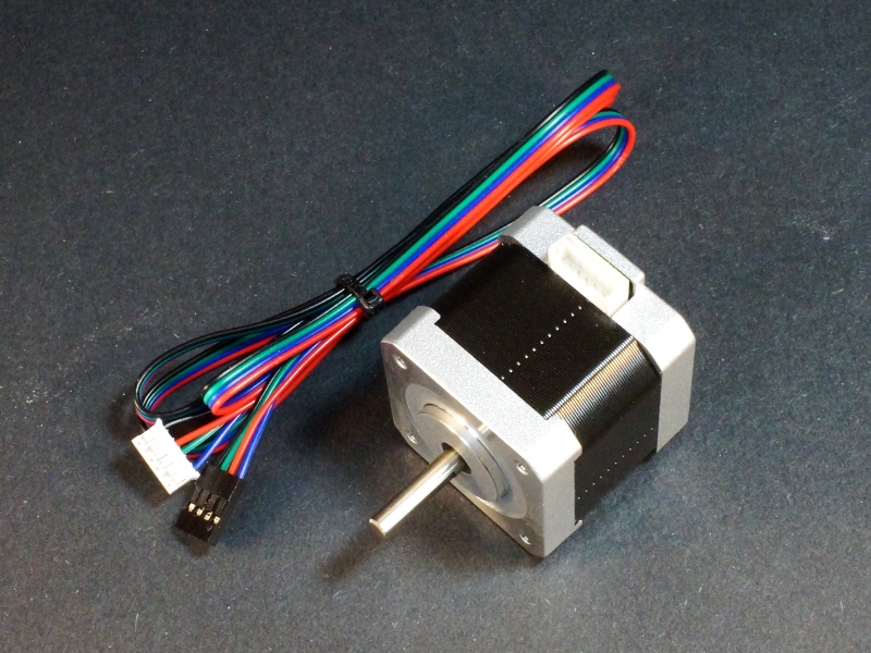
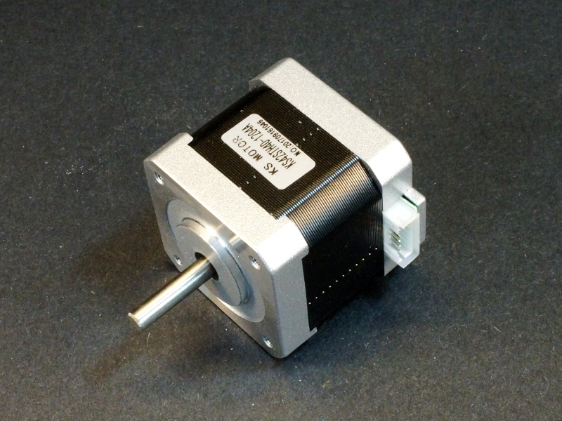
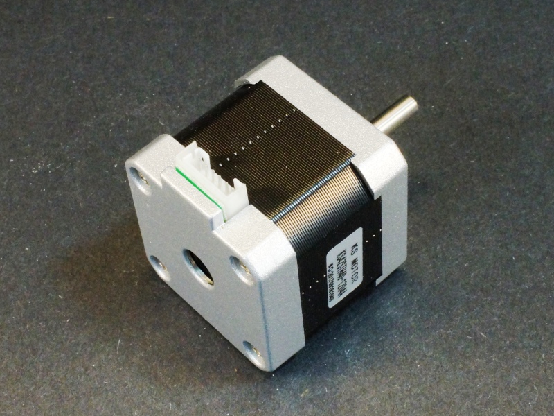
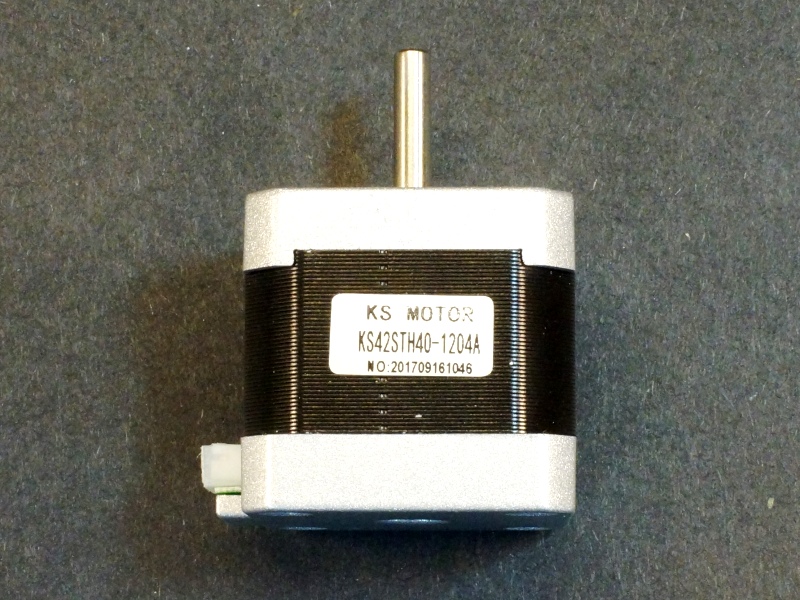
Stepper Motor NEMA-17 1.2A KS42STH40-1204A
$14.95
Precision stepper motor for applications that require precise control.
4 in stock
Description
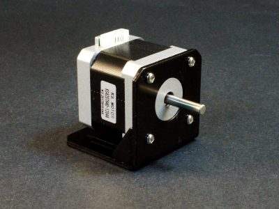
The KS42SH40-1204A is a high quality 1.2A NEMA-17 precision stepper motor that is commonly used in 3D printers, CNC machines and other applications that require precise control.
PACKAGE INCLUDES:
- KS42STH40-1204A Motor
- 4-wire cable 6-pin JST to 4-pin Dupont Female connector – 39″ long
KEY FEATURES OF STEPPER MOTOR NEMA-17 1.2A KS42STH40-1204A:
- 4-wire bipolar operation
- Compatible with NEMA17 standard
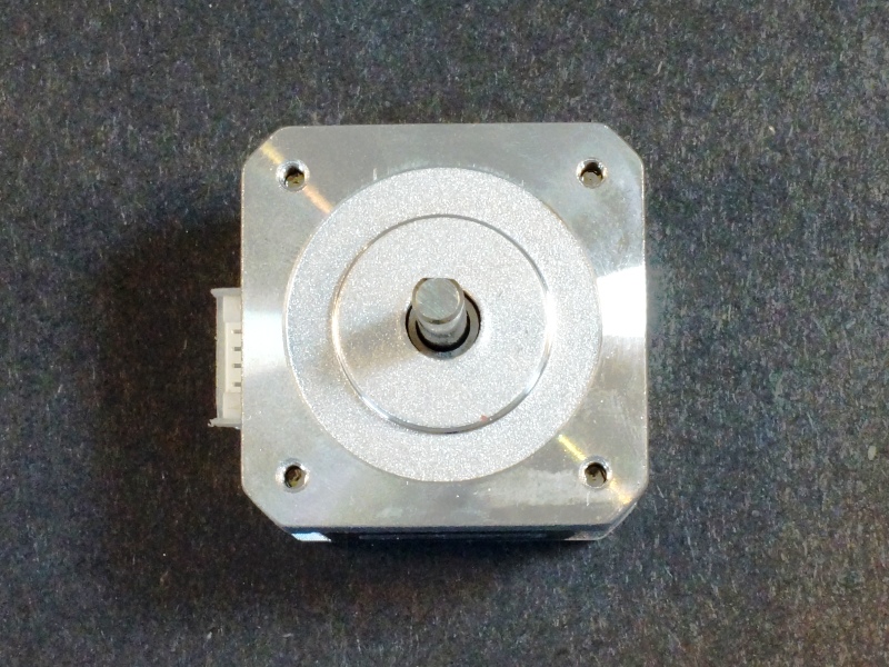
- Dimensions: 42 x 42 x 40mm
- Motor shaft diameter: 5mm
- Step angle: 1.8 degrees
- Step Count per revolution: 200
- Standard Voltage: 2V
- Phase current: 1.2A
- Phase resistance: 1.7 ohm
- Holding torque: 4N.m (minimum)
- Weight: 290g
Stepper motors draw power to hold their current position even if they are not turning, so they tend to be power hungry. They are best suited for being driven off a power supply rather than batteries unless you are using batteries with some serious current capability.
Bipolar stepper motors require two full H-Bridges to drive them unlike unipolar steppers so they are best paired with a good bipolar driver to drive them. These drivers have active current limiting built-in and allow for the motors to be driven from voltages much higher than their rated voltage (2V in this case) which gives improved performance. What is important in these motors is to not exceed their maximum current capability (1.2A in this case), but you can run them at 12V or higher without any problems.
These drivers also allow for micro-stepping which allows you to move the stepper just a fraction of a full step. The motor has 200 full steps for one rotation, but the DRV8825 driver for instance allows you to also use between 1/2 to 1/32 micro-steps, so the 200 full steps can become up to 6400 micro-steps for making one full rotation thus providing much greater precision if it is needed.
Motor Connections:
These are bipolar stepper motors with 4 wires. Direction of rotation is expressed as you are looking at the output shaft. Positive commands turn the motor clockwise. If the motor is rotating in the opposite direction than you intended, simply swap the leads to one coil only.
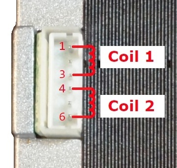
Cable colors may vary. When looking at the connector on the motor, it is 6 pin, but only 4 of the pins are used. Pins 1 & 3 are for one coil and pins 4 & 6 are the other coil.
OUR EVALUATION RESULTS:
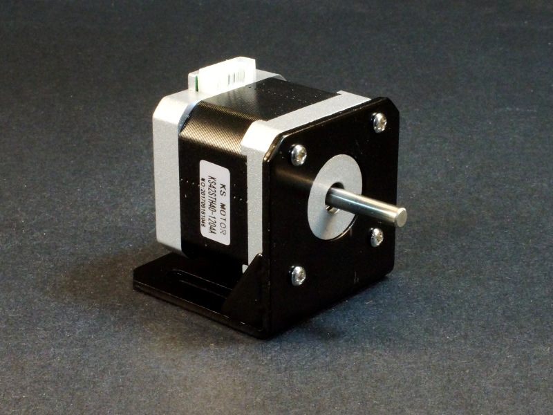
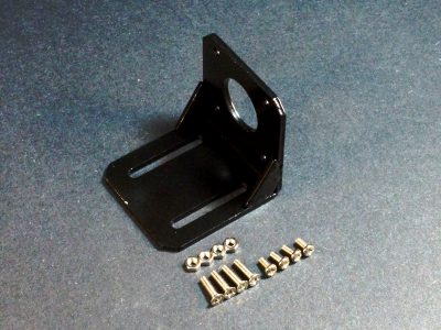
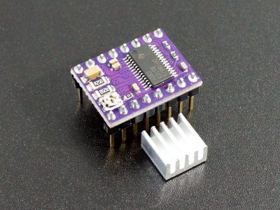
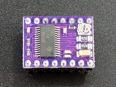
These stepper motors are well made, have good torque and are very smooth in operation. They work great with our DRV8825 Stepper Motor Driver down below. We also have an optional steel bracket which is painted black that can be used for mounting the motor for some applications if you are building something from scratch.
The example software below uses the DRV8825 to drive this servo motor to show the basic mechanics of making one of these things go. More information can be found on the DRV8825 page linked down below.
When using with an Arduino, the BasicStepperDriver.h library can be downloaded from GitHub which provides control for the DRV8825 and similar stepper drivers and is used in our program below.
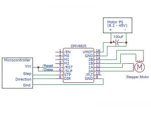
The program is a simple test program. It uses the driver module in the minimal hardware mode using just the DIR and STEP pins with the micro-stepping set to the default of full step as shown in the drawing to the right.
It moves the stepper in one direction for 5 rotations, rotates in the reverse direction for 1 rotation and then rotates for one rotation in discrete individual full steps. Ensure that the RST and SLP pins are pulled up to Vcc on the Arduino. Also ensure that the current limiting has been adjusted for the motor you are using.
Stepper Motor KS42STH40-1204A / DRV8825 Test Program
/*
 * Exercise the DRV8825 Stepper Motor Driver Module
 *
 * This uses the minimal setup configuraiton with DIR connected to pin 8 and
 * STEP connected to pin 9.
 *
 * The /Reset and /Sleep pins need to be pulled up to VCC
 * Step size is left at default of Full Step
 * This uses the BasicStepperDriver.h library which can be downloaded at GitHub
 */
#include <Arduino.h>
#include "BasicStepperDriver.h"

// Motor steps per revolution. Most steppers are 200 steps or 1.8 degrees/step
const int MOTOR_STEPS = 200;
// Set speed of rotation
const int RPM = 120;

// Using default step size. 1=full step, 2=half step, etc.
const int MICROSTEPS = 1;

// Define Arduino pins usedUses default full step
const int DIR_PIN = 8;
const int STEP_PIN = 9;

// Create stepper object in 2-wire basic configuration.
BasicStepperDriver stepper(MOTOR_STEPS, DIR_PIN, STEP_PIN);

//===============================================================================
//  Initialization
//===============================================================================
void setup() {
    stepper.begin(RPM, MICROSTEPS);  // Uses default full step mode
}
//===============================================================================
//  Main
//===============================================================================
void loop() {
   int i;
     for(i=0; i<5; i++) stepper.rotate(360);  // 360 = degrees rotation

    stepper.rotate(-360);   // Rotate once in opposite direction

    for(i=0; i<200; i++){ // Rotate 1 step at a time, pause between steps
      stepper.move(1 * MICROSTEPS); // Steps are full steps
      delay(25);
    }
    delay(1000);
}
BEFORE THEY ARE SHIPPED, THESE MOTORS ARE:
- Inspected
- Packaged for safe shipping.
Notes:
- None
Technical Specifications
| Model | KS42STH40-1204A | |
| Standard Compatibility | NEMA-17 | |
| Phase Number | 2 (bipolar) | |
| Lead Wires | 4 (4 pins of 6-pin JST connector are used) | |
| Operating Ratings | Standard Voltage | 2.0VDC |
| Current per phase | 1.2A | |
| Phase Resistance | 1.7 ohms | |
| Holding Torque | 0.4N.m (minimum) | |
| Step Angle | 1.8 degrees | |
| Step Count | per 360 degree rotation | 200 |
| Dimensions | ||
| Case W x H x L | 42 x 42 x 40mm (1.65 x 1.65 x 1.57″) | |
| Shaft Diameter | 5mm (0.2″) | |
| Shaft Length | 22mm (0.87″) | |
| Mounting Threads | 31mm (1.22″) square mounting holes | M3 (x4) |
| Weight | 290g |

