Sound Sensor Module
$2.95
Detects sound and outputs amplified version of sound waveform
15 in stock
Description
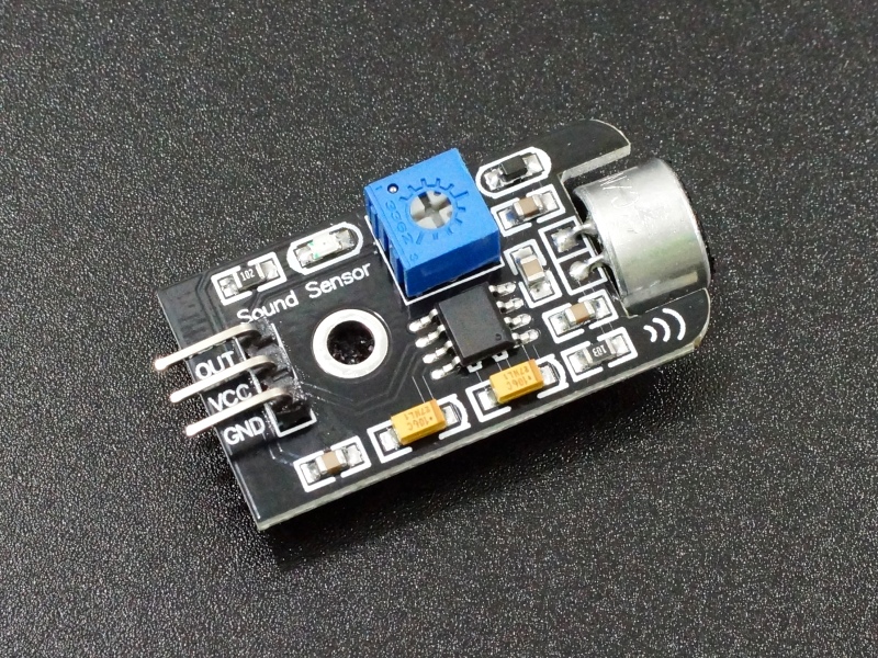
The Sound Sensor Module detects sound waves and outputs an amplified analog version of the waveform
PACKAGE INCLUDES:
- Sound Sensor Module
KEY FEATURES OF SOUND SENOR MODULE:
- Microphone has frequency range of 50 Hz – 13 kHz
- Output is an amplified analog waveform which is adjustable
- 5V operation
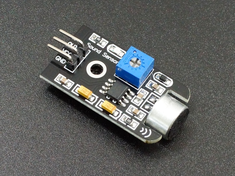
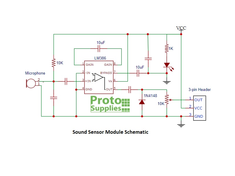
This module incorporates a microphone and an LM386 audio amplifier IC that provides an amplified analog output of the sound waveform.
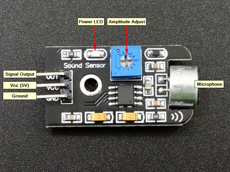
A potentiometer allows the output amplitude to be adjusted. Turning the potentiometer CCW increases the output amplitude.
The potentiometer is on the output of the LM386 and forms a voltage divider to adjust the output amplitude so the LM386 does not provide enough current to drive a speaker directly. The output is intended to drive an analog input of a MCU or other circuit with a fairly high impedance input.
The Vcc specification for the LM386 is 4-12VDC. If using with a 5V MCU, the module should also be operated at 5V. The board has a red LED which lights whenever power is applied.
Module Connections
The module has a 3-pin header on the assembly for making connections.
1 x 3 Header
- OUT = Analog output, typically connects to analog input on MCU
- VCC = 4 – 12VDC (5V typical)
- GND = Ground
OUR EVALUATION RESULTS:
This is a useful module for experimenting with sound or taking an action based on detecting a sound of some magnitude. It can also be used to buffer and feed the sound waveform into another circuit.
Sensitivity of the microphone is decent. We measured a frequency range of about 50Hz to 13KHz. The scope capture below shows the analog output when the microphone picked up a 1KHz sound from a tone generator.

Sound Sensor Module – 1KHz Waveform
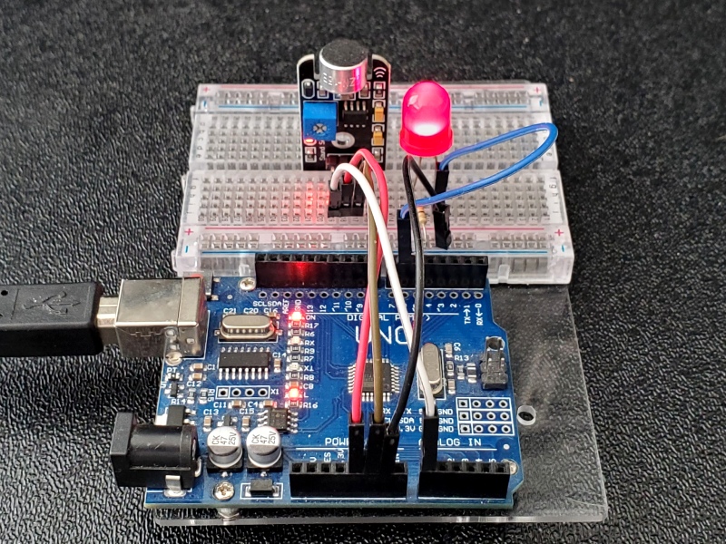
The test program below uses an analog input on the MCU to read the output of the sound sensor module and then use PWM to light an LED so that the LED intensity is relative to the sound level that has been detected. Louder sound should equal brighter LED.
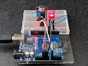
To hook things up, connect the OUT pin on the module to A0 or other analog input on the MCU. Also wire up VCC to 5V and GND to ground. Note that the right angle header is mounted inboard enough that it will not plug into a solderless breadboard unless the PCB portion is inserted in the channel in the middle of the breadboard as shown in the picture.
Next you will need to connect the anode of an LED to D6 or any digital pin on the MCU that can support PWM. Be sure to use a series current limiting resistor. Anything between 240 and 680 ohms will work fine. The cathode of the LED (shorter lead) connects to ground.
We assume that the analog waveform magnitude out of the module will be mostly on the low side, so we constrain it which means that any input measured above 128 on the analog pin will be set to 128.
The measured sound range of 0-128 is then mapped to the LED PWM range of 0-255, so an input of 128 or greater will give a PWM of 255 which will turn the LED full on. The constrain numbers may need to be played with depending on the amplitude of the sound that is being monitored. You can send the sensorValue to the Serial Monitor window to see what values are actually being measured.
Sound Sensor Test Program
/*
Sound Sensor Test

Measure input from sound sensor module and set the
LED brightness to match the sound volume picked up by the microphone
Louder sounds = brighter LED.
Constrain range can be adjusted depending on expected sound volume
*/
int sensorPin = A0;   // microphone sensor input
int ledPin = 6;       // select PWM pin for the LED.
int sensorValue = 0;  // variable to store the value coming from the sound sensor
//===============================================================================
//  Initialization
//===============================================================================
void setup() {

}
//===============================================================================
//  Main
//===============================================================================
void loop() {
  sensorValue = analogRead(sensorPin);          // Read module output
  sensorValue = constrain(sensorValue, 0, 128); // constrain to lower end of range
  int ledbrightness = map(sensorValue, 0, 128, 0, 255); // Map value to PWM
  analogWrite(ledPin, ledbrightness);         // Set LED brightness
}
BEFORE THEY ARE SHIPPED, THESE MODULES ARE:
- Sample inspected and tested per incoming shipment.
Notes:
- None
Technical Specifications
| Maximum Ratings | ||
| Vcc | 4-12VDC (5V typical) | |
| Operating Ratings | ||
| Microphone | Lowest Range | 50Hz (measured) |
| Highest Range | 13KHz (measured) | |
| Dimensions | L x W (PCB) | 36 x 20mm (1.4 x 0.78″) |
| Country of Origin | China |

