Slide Potentiometer Dual 5K Logarithmic Module
$4.49
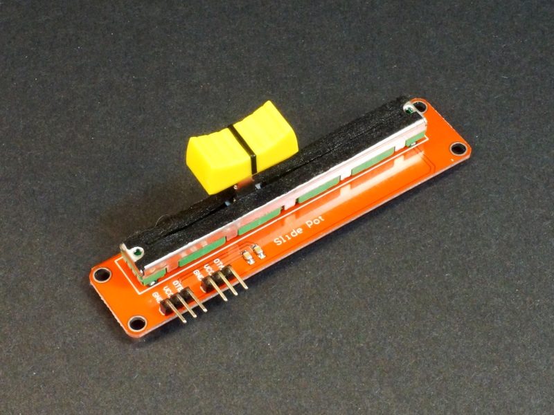
The Slide Potentiometer Dual 5K Logarithmic Module presents an interesting user interface option for some applications
Out of stock
Description
The Slide Potentiometer Dual 5K Logarithmic Module presents an interesting user interface option for some applications
PACKAGE INCLUDES:
- Slide Potentiometer Dual 5K Logarithmic Module
KEY FEATURES OF SLIDE POTENTIOMETER DUAL 5K LOGARITHMIC MODULE:
- Dual 5K potentiometers
- Logarithmic taper from the center position
- 3.3 and 5V logic compatible
Slide potentiometers present an interesting user interface which can be more intuitive than typical rotating potentiometers and can be quite useful in some applications.
The potentiometer has a logarithmic taper from the center position. This means that the center range of the potentiometer has more change in resistance as the slider is moved than do the two outer ends of the range. This type of potentiometer is commonly used when controlling audio and can also be handy when controlling something such as a motor where you may want to slow the rate of change as the motor approaches its limits either at stop or full speed. You could imagine two of these being a nice intuitive way to control the two treads on a tank chassis.
Module Connections
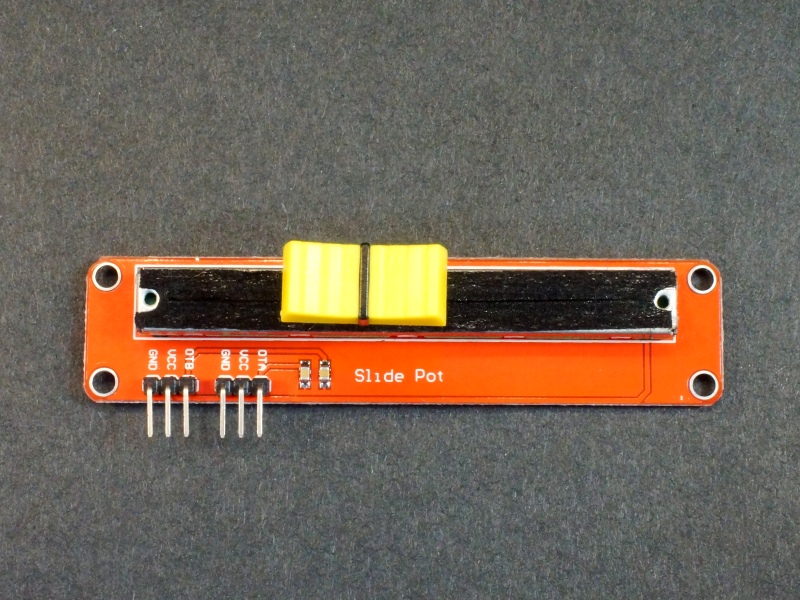
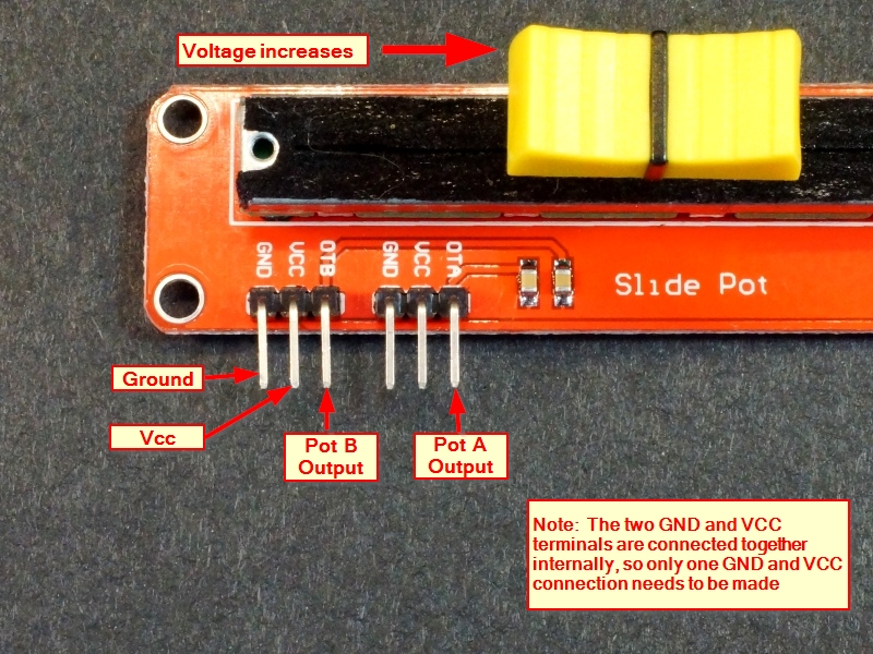
There are two header connectors on the board, one for each pot. Note that the two Ground pins are connected together on the module as are the VCC pins, so it is only necessary to connect power and ground to one of these connectors.
Since the power and ground are the same, the two potentiometer outputs will be nearly identical. In most applications, connecting to just one of the headers / pots will be the normal way to use the module. VCC is generally connected to the same voltage as the uC when used with a uC, but it can be connected to an arbitrary voltage such as 12V. The output voltage will range from 0V up to VCC.
1 x 3 Header (x2)
- GND – Connect to system ground. This ground needs to be in common with the uC.
- VCC – Connect to Vcc. This will typically be the voltage (3.3 or 5V) that the uC is operating at.
- OTA / OTB – The output of the potentiometers. Typically connected to an analog input pin on the uC.
OUR EVALUATION RESULTS:
These slider pots have good functionality based on our testing with fairly smooth operation over their range. We haven’t noted any jumpiness or dead-spots. Minimum resistance was measured at < 1 ohm while maximum resistance is the rated 5K value ±5%.
The rated current of these modules is not known, but in general should be used to drive analog inputs on a microcontroller. They are not suitable for controlling a motor speed directly or other high current application.
The program below is handy for getting a good feel for how the slider works. The raw DAC reading, the voltage as measured by the DAC and the calculated resistance is printed out to the Serial Monitor as the slider is moved.
The slider pot output is connected to A0 in our example, but it can be any analog input.
Slide Potentiometer Dual 5K Logarithmic Module Example Software
/*
 * Potentiometer Test
 *
 * Reads input of pot on ADC pin and prints out the raw ADC data, the corrosponding voltage
 * and the calculated resistance.
 */
const int POTPIN = A0;    // Set to analog pin being used
const float VCC = 5.0;    // Set to Vcc of microprocessor. Usually 3.3 or 5.0
const float POTVAL = 5000.0;  // Set to max resistance of the pot

int RawPotValue = 0;
float Voltage = 0.0;
float Resistance = 0.0;

//===============================================================================
//  Initialization
//===============================================================================
void setup() {
  pinMode(POTPIN, INPUT);
  Serial.begin(9600);
}
//===============================================================================
//  Main
//===============================================================================
void loop() {
  RawPotValue = analogRead(POTPIN);
  Voltage = (RawPotValue * VCC) / 1024.0;   // Convert 10-bit ADC reading to voltage
  Resistance = POTVAL * (RawPotValue / 1024.0); // Calculate resistance value

  Serial.print("Raw Pot Value = " );  // shows raw reading as measuerd by ADC
  Serial.print(RawPotValue);
  Serial.print("t Voltage = ");  // shows the voltage measured to 3 digits after decimal point
  Serial.print(Voltage,3);
  Serial.print("t Resistance = ");   // shows the calculated resistance
  Serial.println(Resistance);
  delay(1000);                        // delay 1 sec between readings
}
BEFORE THEY ARE SHIPPED, THESE MODULES ARE:
- Inspected
- Basic operation verified
- Packaged in a resealable ESD bag for protection and easy storage.
Notes:
- None
Technical Specifications
| Value | 5K (x2) | |
| Wattage | Unknown | |
| Taper type | Logarithmic | |
| Adjustment Type | Top mounted slider | |
| Dimensions | L x W x H | 91 x 21 x 30mm |
| Mfr | China |


